Converting rear drum brakes to disc brakes takes more than bolting on a rotor and caliper. You need compatible mounting hardware, the right parking brake cables and hoses, and a hydraulic system that delivers the correct pressure to the new brakes.
I’m doing this conversion on a Honda Del Sol S using aftermarket adapter brackets and brake components intended for the disc-equipped Del Sol Si. Most of the work uses common hand tools, but old bearings and heavy rust can add a few challenges. I’ll cover those, too, along with the brake pressure measurements and before-and-after stopping tests.
Brakes are safety-critical. Use the service information for your exact vehicle and the instructions supplied with your conversion kit. The torque values below apply to this Honda and this particular kit, not every drum-to-disc conversion. If you find structural corrosion, damaged brake lines, or anything you cannot confidently repair, stop and get qualified help before driving.
What You'll Learn
- Factory disc assemblies and aftermarket adapters offer two routes to a rear drum-to-disc conversion.
- Matching parking brake cables, hoses, and hydraulic proportioning are essential parts of the conversion.
- Flat mounting surfaces and correct caliper alignment matter as much as proper bolt torque.
- This Honda’s consistent stopping distances improved by about 30 feet after the complete conversion.
Table of Contents
- 1. Choose Your Drum-to-Disc Conversion Parts
- 2. Gather Tools and Establish a Braking Baseline
- 3. Safely Raise the Car and Remove the Drum
- 4. Remove the Hub, Shoes, and Backing Plate
- 5. Replace the Parking Brake Cables
- 6. Prepare the Caliper Adapter Mounting Surface
- 7. Replace the Hub and Deal With a Stuck Bearing Race
- 8. Install the Rotor and Check Caliper Alignment
- 9. Install the Pads, Hardware, and Calipers
- 10. Connect the Parking Brake Cable to the Caliper
- 11. Replace and Connect the Brake Hoses
- 12. Bleed Both Rear Calipers
- 13. Replace the Proportioning Valve and Bleed the Full System
- 14. Perform Final Checks Before Driving
- 15. Drum Brakes vs. Disc Brakes: The Stopping Test Results
1. Choose Your Drum-to-Disc Conversion Parts
There are two main ways to gather the parts: use factory disc brake assemblies from a compatible higher trim level, or use an aftermarket conversion kit.
Option 1: Factory parts from a higher trim level
The Del Sol S has rear drum brakes, while the Del Sol Si came with rear discs. A compatible Si trailing arm assembly already has the factory disc brake mounting arrangement.
With this approach, you remove the original trailing arm, install the disc-equipped assembly, and connect the appropriate brake hoses and parking brake cables. It can save you from adapting a drum brake mounting surface, but used assemblies still need inspection. Bearings, bushings, calipers, hoses, and hardware may need attention before installation.
Option 2: Aftermarket adapter brackets
The second approach uses an adapter to mount a disc brake caliper to the existing assembly. That is the method I’m using here so I can install new brake components and work through the whole conversion.
Do not assume a conversion kit contains everything. My kit includes two adapter brackets and fasteners. The calipers, rotors, pads, cables, hoses, and other components are separate.
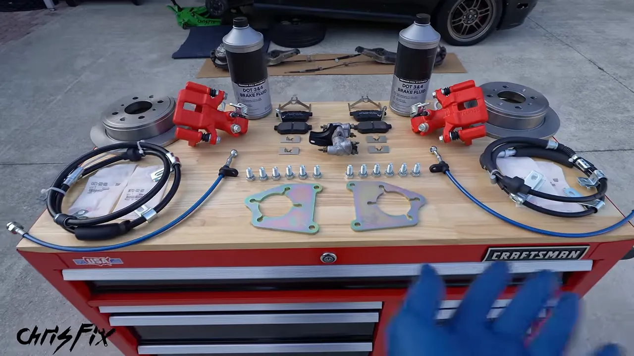
For this Honda, the main parts include:
- Left and right caliper adapter brackets with the specified fasteners.
- Matching rear calipers and caliper brackets.
- Rear brake rotors, pads, and pad hardware.
- Disc brake parking brake cables.
- Compatible flexible brake hoses and mounting hardware.
- New banjo bolt sealing washers.
- A compatible four-wheel-disc proportioning valve.
- Replacement hub and bearing assemblies where needed.
- New spindle nuts and the required retaining clips and pins.
- The correct brake fluid.
Do not overlook the proportioning valve
This is an important part of the conversion. The original hydraulic system was designed around rear drums, and the replacement rear discs need a different pressure arrangement on this Honda.
On this non-ABS car, a separate proportioning valve is mounted near the firewall. I’m replacing it with the matching valve from a Del Sol Si, which had front and rear disc brakes from the factory.
Other vehicles may incorporate proportioning into the master cylinder or use ABS-based brake pressure control. Verify the requirements for your vehicle rather than assuming every conversion needs the same valve swap. An ABS-equipped car is not automatically compatible with any rear disc setup simply because it has ABS.
|
2. Gather Tools and Establish a Braking Baseline
A socket set, ratchets, breaker bar, torque wrench, pliers, punches, hammer, jack, and jack stands handle most of this job. You will also want safety glasses, brake cleaner, collection containers, clear bleeding hose, and tools for cleaning rusty mounting surfaces.
Two tools make the hydraulic work much easier:
- Flare nut wrenches: These wrap around more of the brake line fitting than an ordinary open-end wrench, reducing the chance of rounding it.
- Brake line stoppers: These help limit fluid loss while a line is disconnected.
Ratcheting flare nut wrenches are especially useful around the proportioning valve. Removing its fittings with conventional flare nut wrenches took me roughly 30 to 40 minutes. Reconnecting them with a ratcheting set was much quicker.
The original drum brake stopping distances
Before taking the car apart, I went to Bradenton Motorsports Park for a controlled 60-to-0 mph braking test. I used cones as the braking point and measured from the cones to the centerline of the front tire, giving me a repeatable reference.
After a 141-foot practice stop, the three back-to-back measured stops were:
- First stop: 140 feet.
- Second stop: 141 feet.
- Third stop: 143 feet.
That gives us a baseline of about 141 feet. These tests belong on a closed course, not a public road.
3. Safely Raise the Car and Remove the Drum
- Chock the front wheels so the car cannot roll.
- Loosen the rear lug nuts while the tires are still on the ground.
- Raise the rear using the vehicle’s approved lifting point.
- Place jack stands at approved support points and lower the car onto them.
- Check stability before going underneath.
- Remove the rear wheels.
I leave the jack lightly touching the lifting point as a backup and slide the removed wheel beneath the car as an additional precaution. Neither replaces properly positioned jack stands.
With the wheel off, inspect the suspension. This car has deteriorated bushings and substantial rust, and the rear end already feels loose on the road. A brake upgrade does not fix suspension problems, so those need their own repair plan.
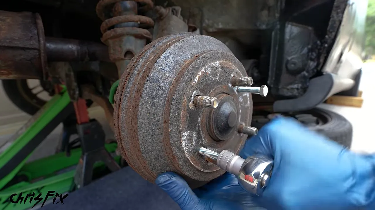
Release the parking brake before removing the drum. If the drum is stuck, controlled hammer taps around its edge may help break the rust bond. Avoid striking the wheel studs.
This drum also has threaded removal holes. Thread the correct bolts into those holes and tighten them alternately, a little at a time, to push the drum away from the hub evenly. Confirm the thread size for your drum rather than forcing in a bolt that seems close.
Avoid breathing brake dust or blowing it into the air. Older friction components may contain asbestos. OSHA’s asbestos safety information provides supporting guidance on the hazard.
4. Remove the Hub, Shoes, and Backing Plate
Remove the hub and bearing assembly
Work a punch or chisel carefully around the hub dust cap to loosen it. Once the cap is off, you can access the spindle nut.
The nut on this Honda has an edge staked into a groove in the spindle. Lift that staked section clear before trying to unscrew it. Then use a 32 mm socket and a breaker bar or suitable long ratchet to loosen the nut.
Remove the nut, save the washer behind it, and slide the hub and bearing assembly off the spindle. Do not lose that washer. Without it, the bearing can remain loose even when the nut feels tight.
Remove the drum brake components
Release the shoe hold-down hardware by pressing the spring retainer inward and turning it until the pin lines up with the opening. Remove the shoes and springs, then disconnect the parking brake cable end from the shoe lever.
The cable housing is retained in the backing plate by spring fingers. A useful trick is sliding the box end of a suitably sized wrench over the retainer to compress those fingers. Then work the cable housing out of the plate.
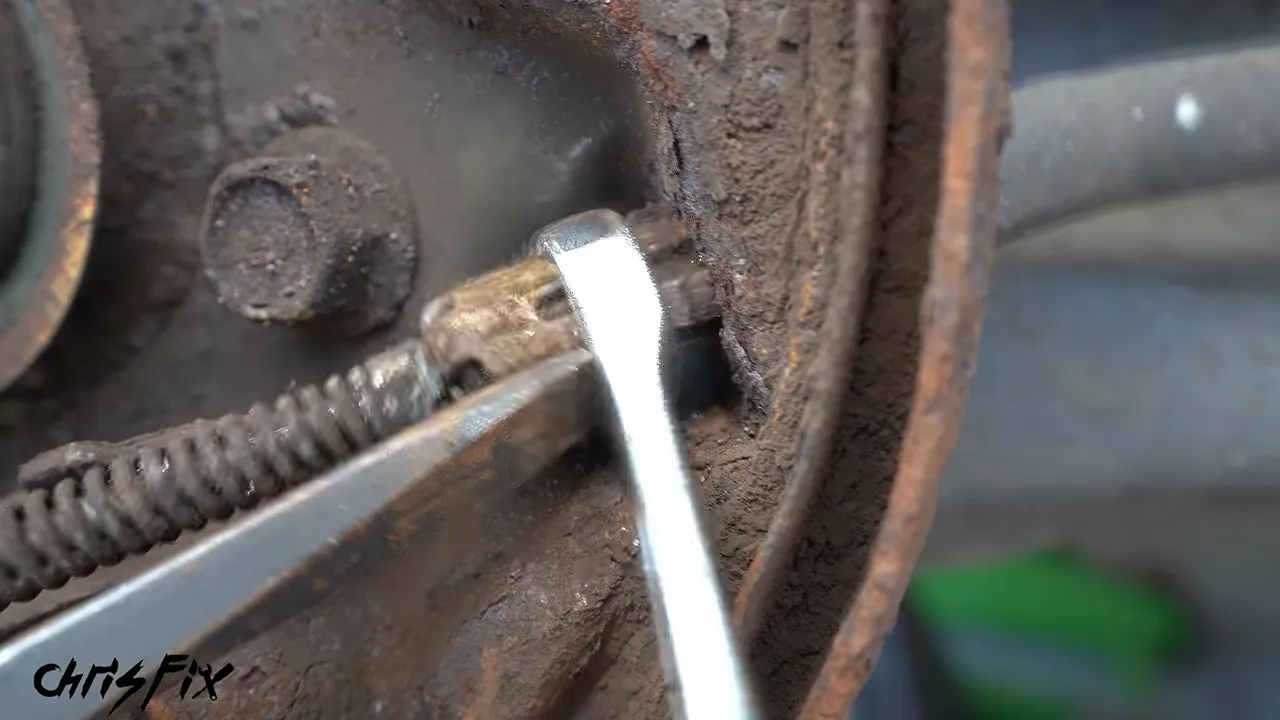
Next, disconnect the hydraulic connection to the wheel cylinder. My old line is badly corroded and is being discarded as part of the conversion, so I cut the section that will be replaced. Do not cut a line you intend to reuse.
Use a suitable stopper to limit fluid loss. I also use a hose pinch-off tool on an old hose that is being replaced. Do not clamp a hose you plan to keep. Pinching can damage it internally without leaving an obvious external warning.
Finally, remove the four backing plate bolts and take the plate off. Clean rust from the bolt heads and make sure the socket is fully seated before applying force. A partially seated socket can round an already weakened fastener.
5. Replace the Parking Brake Cables
The drum and disc parking brake cables look almost identical on this car, but the ends are different. One connects to a drum brake shoe lever; the other connects to the lever on the rear caliper.
Follow the original routing underneath the car before removing anything. On this Honda, each cable has three mounting points, and a heat shield covers access to one of them.
- Remove the cable mounting bolts.
- Remove the heat shield where needed for access.
- Remove the spring at the cable equalizer.
- Align each cable end with the slot in the equalizer bracket and slide it out.
- Free the cable housings from their mounts and withdraw the cables.
Corroded cable housings may need careful tapping to loosen them. Avoid damaging the brackets that must be reused.
With the cables out, I clean loose, flaky rust from the surrounding underbody and apply a rust-treatment coating. Follow the coating manufacturer’s preparation and drying instructions. Paint can protect remaining sound metal, but it does not restore metal lost to corrosion.
Once the coating is dry, install the new cables in the original route. Seat the housings in their mounts, slide the cable ends into the equalizer, turn them into their retained position, and reinstall the spring.
Reattach the mounting brackets and heat shield. At the trailing arm, pull the cable through until its rubber grommet seats fully in the opening.
6. Prepare the Caliper Adapter Mounting Surface
The adapter bracket must sit flat against its mounting surface. Thick, bubbling rust can hold it at an angle, misaligning the caliper and potentially causing contact or vibration.
I use a wire wheel to remove the scale, then work carefully on stubborn raised areas before checking the bracket fit again. The goal is a clean, flat mounting surface, not grinding away sound metal.
Test-fit the adapter before bolting it down. It should sit flush without rocking or visible gaps.
What if cleaning exposes a rust hole?
Cleaning this assembly uncovered a hole in the trailing arm near the brake mounting area. I filled it with MIG weld during this project and planned to replace the complete suspension assembly afterward.
Do not treat a quick weld as a general repair method for a rusted suspension component. A filled hole alone does not establish that the surrounding metal is structurally sound. Corrosion in a brake or suspension mounting area calls for replacement or assessment and repair by a qualified professional before road use.
Welding also requires much more than disconnecting the battery. Electrical protection, fire prevention, coatings, nearby hoses, and solvent residues all need attention. Keep brake cleaner and other chemicals away from welding and hot work.
Install the adapter
Once the mounting area is sound, prepared, and protected as directed, position the adapter and start all four bolts by hand.
For this kit, I apply medium-strength threadlocker, tighten the bolts progressively in a crisscross pattern, and torque them to 45 ft-lb. Follow your kit’s requirements for fasteners, thread treatment, and torque.
7. Replace the Hub and Deal With a Stuck Bearing Race
When I removed the old hub, its inner bearing race stayed on the spindle. The old bearing’s grease was dried out, and with everything already apart, replacing the hub and bearing assembly made sense.
A stuck race can be difficult to remove without damaging the spindle. In this case, I cut a shallow diagonal groove into the race and used a chisel to drive it outward. The first attempt broke a piece off the race, so I made another groove and used controlled heat on the race before trying again.
The critical point is protecting the spindle. Do not cut into it, hammer its bearing surface, or expose nearby hoses and wiring to heat. A suitable bearing separator or professional removal is preferable if you cannot remove the race safely.
After removing the race, allow everything to cool, clean the spindle, and inspect it before installing the new hub.
- Slide the new hub and bearing assembly into place.
- Install the original required washer.
- Start a new spindle nut by hand.
- Tighten it using the vehicle’s specified procedure and thread condition.
- Stake the nut into the spindle groove where required.
- Reinstall the dust cap.
The spindle nut torque on this Honda is 134 ft-lb. Correct torque matters because overtightening or undertightening can damage the bearing. I used medium-strength threadlocker during this installation, but that is not a universal bearing installation requirement. Follow the service procedure for your assembly.
8. Install the Rotor and Check Caliper Alignment
Before installing a new rotor, clean any shipping oil or protective residue from both braking faces using brake cleaner and clean towels, unless the rotor manufacturer specifies a different preparation method. Keep that residue away from the new pads.
Slide the rotor onto the hub and use two lug nuts to hold it flat against the hub while checking the caliper bracket fit.
Start the caliper bracket bolts by hand, then rotate the rotor. Check that it turns without contacting the bracket and inspect the clearance on both sides.
On my assembly, one side was too close while the other had a noticeably larger gap. Removing heavy corrosion had changed the mounting position enough to move the bracket inward.
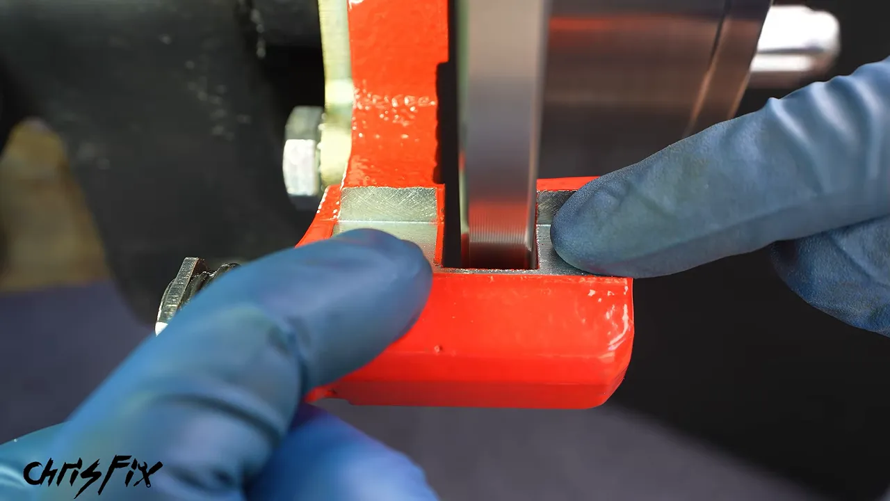
I corrected this installation with 1 mm stainless steel washers used as shims at both bracket mounting bolts. That moved the bracket outward and improved the clearance.
Shimming is not a universal fix. Use only a spacing method allowed by the conversion manufacturer, and verify fastener engagement and alignment. If the bracket is significantly out of position, investigate the cause rather than stacking washers until it appears to fit.
For this setup, the caliper bracket bolts are torqued to 28 ft-lb with medium-strength threadlocker.
9. Install the Pads, Hardware, and Calipers
Fit the new pad hardware into the caliper bracket. The pads should slide correctly in the hardware without binding.
I use a very thin coating of copper anti-seize on the metal contact points in this installation, including the pad ears and backing plate contact areas. For your brakes, use the lubricant and application points specified by the brake manufacturer. Do not assume anti-seize is appropriate for every pad, shim, coating, or rubber component.
Keep all lubricant off the pad friction material and rotor braking faces. More is not better. Excess material can migrate where it does not belong.
The pad with the mechanical wear indicator goes on the inside of this Honda caliper. Check the pad instructions for your application because wear indicator positions can differ.
Install the pads, fit the remaining specified hardware, and slide the caliper over them. Start both slide pin bolts by hand, then torque them to 17 ft-lb for this setup.
Make sure the bleeder is at the top
The left and right calipers must be on the correct sides. My caliper is marked with an R, but the useful visual check is the bleeder position.
The bleeder must be at the top of the caliper’s fluid cavity. Air rises, so a caliper installed with the bleeder down low can retain air even after repeated bleeding.
10. Connect the Parking Brake Cable to the Caliper
Feed the cable housing through the caliper’s cable bracket. On this installation, a 12 mm E-type retaining clip fits into the housing groove. Seat it completely.
Next, align the cable end with the hole in the caliper’s parking brake lever. A wrench on the lever gives me enough leverage to move it while keeping my other hand free to line up the holes.
Insert the connecting pin, then install the cotter pin that prevents it from coming out. Check that the cable housing, retaining clip, connecting pin, and cotter pin are all secure.
11. Replace and Connect the Brake Hoses
The floating disc brake caliper needs a compatible flexible hose. The original drum brake plumbing is not reused unchanged.
Disconnect the old hose without damaging the hard line
Clean rust and dirt from the connection before loosening the flare nut. Use penetrating fluid according to its instructions, then use a flare nut wrench while supporting the adjoining fitting as needed.
The fitting should turn without twisting the hard line. If the line begins to twist, stop. Forcing it can turn a hose replacement into a hard line repair.
I used heat on some corroded fittings during this project. That is not a casual step around brake hoses, fluid, coatings, or penetrating chemicals. In particular, the acetone and transmission fluid mixture used here is flammable. Never apply flame near penetrating fluid or solvent vapors.
Once disconnected, cap or stop the hard line to limit drainage. Remove the hose retaining clips and mounting hardware.
One old hose fitting was seized so tightly into its bracket that I could not remove it on the car. I unbolted the bracket and worked on it at the bench, then cleaned and painted the bracket before reinstalling it.
Route the new hose
Install the replacement hose through its proper mounting points and secure the retaining clips. My hose has a plastic mounting section, so I tighten that mount only enough to secure it without crushing the plastic.
Keep the open hose ends clean using suitable clean plugs. Start the hard line flare nut by hand, hold the mating fitting with a second wrench, and tighten according to the hose and vehicle specifications.
I used a small amount of anti-seize on the external flare nut threads during this installation. Follow the fitting manufacturer’s instructions for your application, and keep any compound off the flare seat and out of the hydraulic system.
Flush the hose and install the banjo bolt
Before connecting the hose to the caliper, I let fluid drain into a container until the fluid coming through looks clean. Keep checking the master cylinder reservoir so it never runs dry.
This Honda accepts DOT 3 or DOT 4 fluid as specified for the car. Use the fluid required by your vehicle rather than choosing solely by the DOT number.
The banjo connection needs two new sealing washers: one between the bolt head and hose fitting, and one between the hose fitting and caliper.
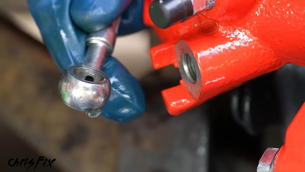
Thread the bolt in carefully without cross-threading it. The banjo bolt torque for this setup is 25 ft-lb. These washers form the hydraulic seal, so do not omit one or try to compensate for a leak by overtightening.
12. Bleed Both Rear Calipers
With the hose connected, it is time to remove the air from the caliper.
I apply a small amount of compatible grease to the external bleeder threads to help limit air entering around them and reduce future corrosion. Keep grease away from the bleeder’s sealing tip and internal passage. The bleeder seals at its seat, not at its threads.
Fit a wrench over the bleeder and attach clear hose. I use tubing with a 3/16-inch inside diameter so I can see the bubbles leaving the caliper.
- Have a helper press and hold the brake pedal.
- Open the bleeder briefly to release fluid and air.
- Close the bleeder before the helper releases the pedal.
- Repeat until the fluid is bubble-free.
- Check and replenish the reservoir throughout the process.
Having the helper pump the pedal several times before holding it helped move trapped air during this installation. One caliper took about eight cycles, but the number is not a target. Continue until the air is removed and the pedal condition is correct.
Clean the bleeder, replace its dust cap, and repeat the conversion on the other rear wheel.
13. Replace the Proportioning Valve and Bleed the Full System
Measure the original rear brake pressure
With the rear disc components installed but the drum brake proportioning valve still in place, I connected a brake pressure gauge at the rear caliper.
After bleeding the gauge connection, a hard pedal application produced approximately 700 psi.
This was a comparison measurement for this project, not a universal brake pressure specification. Pedal effort affects the reading. Use properly rated brake testing equipment and compatible adapters.
Install the disc brake valve
Place an absorbent mat beneath the proportioning valve because disconnecting the lines will release fluid. Protect painted surfaces and keep dirt out of every open connection.
- Clean the fittings and loosen the flare nuts with the proper wrench.
- Disconnect the lines carefully without bending or twisting them unnecessarily.
- Remove the valve’s mounting nuts.
- Install the compatible replacement valve.
- Start all line fittings by hand before tightening them.
- Secure the fittings and mounting hardware to the applicable specifications.
One rusty mounting stud snapped during removal. Cleaning the remaining threads before loosening their nuts helped the other fasteners come off more easily.
I retained the valve on the remaining threads during this project, but threadlocker does not replace adequate thread engagement or a sound mounting stud. Repair damaged mounting hardware properly so the valve and lines are securely supported.
Refill the reservoir, then have a helper apply the brakes while you inspect every valve connection for leaks.
Bleed all four brakes
Opening the proportioning valve connections introduces air farther upstream, so both rear calipers alone are no longer enough. Bleed the complete system using the vehicle’s specified sequence.
The order used on this Honda is:
- Passenger-side rear.
- Driver-side rear.
- Passenger-side front.
- Driver-side front.
Do not stop simply because the first fluid leaving the bleeder looks bubble-free. Air introduced near the front of the car has to travel through the lines before it reaches the rear bleeders.
Keep topping up the reservoir. Letting it run dry introduces more air and adds work. Once finished, fill to the proper full mark and reinstall the reservoir cap.
Check the pressure difference
With the disc brake proportioning valve installed and the system bled, the rear gauge reading increased to approximately 1,100 psi, compared with 700 psi before the valve change.
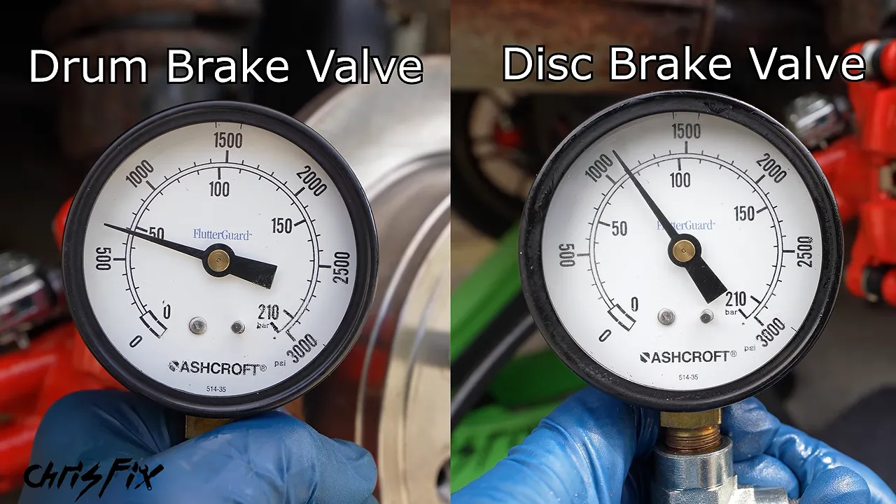
That is roughly a 60 percent increase in this comparison. It shows why hydraulic compatibility matters just as much as getting the new calipers bolted on.
14. Perform Final Checks Before Driving
Before the car moves, work through the completed installation carefully:
- Confirm the pedal is firm and does not continue sinking under steady pressure.
- Inspect the proportioning valve, hose connections, banjo bolts, and bleeders for leaks.
- Confirm both calipers have their bleeders at the top.
- Check that hoses and cables are secure and cannot rub, stretch, or kink.
- Verify the parking brake applies and releases correctly.
- Confirm the rotors rotate without unintended bracket contact.
- Reinstall the wheels and torque the lug nuts to the vehicle specification.
- Check the brake fluid level one more time.
Do not drive with a soft pedal, a leak, a dragging brake, or unresolved structural damage. Begin with controlled low-speed checks in a safe area, and follow the pad and rotor manufacturer’s bedding procedure before demanding full braking performance.
15. Drum Brakes vs. Disc Brakes: The Stopping Test Results
Back at the track, the first three 60-to-0 mph stops with the new rear discs measured 137 feet, 133 feet, and 129 feet.
At first, that was a little disappointing compared with the original roughly 141-foot baseline. But the distances kept getting shorter. My interpretation was that the new pads and rotors were bedding in.
Once the distances became consistent, the next three stops measured:
- First stop: 111 feet.
- Second stop: 112 feet.
- Third stop: 111 feet.
That is about 30 feet shorter than the drum brake baseline, or roughly two car lengths in this test.
These are the results for this car, with its original brake condition, replacement components, and revised proportioning valve. They are not a promise that every rear disc conversion will reduce stopping distance by the same amount.
The finished setup also looks much cleaner, and replacing pads and rotors later will be more straightforward than servicing the old drum assembly. But the important part is the complete system: compatible components, sound mounting surfaces, correct alignment, suitable hydraulic pressure, secure connections, and thorough bleeding. Get those details right, and this becomes much more than a cosmetic upgrade.


