A puff of bluish-white smoke when you start your car is not something to ignore. If the smoke clears shortly afterward, leaking valve stem seals could be letting oil run down the valves while the engine sits. That oil burns off at startup, leaving a cloud behind the car.
The good news? On the Honda engine I’m repairing here, the valve stem seals can be replaced without removing the cylinder head. With common hand tools, a few specialty tools, and a methodical approach, this is a repair you can tackle at home.
My local Honda dealership quoted $2,187 for valve stem seal replacement and a valve lash adjustment, with seven hours of book labor. The parts, supplies, and inexpensive tools laid out for this repair came to about $150. That’s a potential savings of over $2,000, depending on what you already own and what your engine requires.
We’re going to cover the complete job: diagnosing the leak, supporting the valves with compressed air or rope, replacing the seals, checking cylinder leak-down, adjusting valve lash, and sealing everything back up.
Important: This is a 1.5-liter Honda engine with 16 valves and over 200,000 miles. The principles apply to many engines, but access, timing procedures, tools, torque specifications, and valve clearances vary. Use your vehicle’s service manual alongside these instructions. All specifications below are for this particular engine, not universal settings.
What You'll Learn
- A brief puff of bluish-white startup smoke can indicate leaking valve stem seals.
- Compressed air or clean rope supports the valves during seal replacement without removing the cylinder head.
- Protective sleeves, blocked openings, and correctly seated keepers help prevent costly mistakes.
- Leak-down testing, valve lash adjustment, and fresh gaskets complete the repair.
Table of Contents
- Recognize the Signs of Leaking Valve Stem Seals
- Why Burning Oil Can Become an Expensive Problem
- Tools and Parts You’ll Need
- 1. Remove the Valve Cover and Expose the Valvetrain
- 2. Remove the Rocker Arm Assembly Carefully
- 3. Position the Piston and Block Open Passages
- 4. Hold the Valves Closed with Compressed Air
- 5. Replace Each Valve Stem Seal
- Other Ways to Remove and Install Valve Keepers
- 6. Use Rope If You Don’t Have an Air Compressor
- 7. Check Cylinder Health with a Leak-Down Test
- 8. Replace the Rocker Assembly Seals and Reinstall It
- 9. Check and Adjust Valve Lash
- 10. Reassemble the Engine and Check the Repair
Recognize the Signs of Leaking Valve Stem Seals
The pattern to look for is straightforward: the engine starts, produces a puff of oily smoke, and then clears up. The amount of smoke can vary considerably.
I compared cold starts from a Toyota Celica, Chevy Suburban, Suzuki, Datsun, and my Driftstang. Some produced a substantial cloud; others had a much smaller puff. The common feature was smoke at startup that then went away.
That pattern is a useful clue, not a reason to immediately take the engine apart. Confirm where the oil is coming from before committing to valve stem seal replacement.
What a leaking valve seal looks like inside the engine
To show the problem directly, I let the Honda cool completely and removed the exhaust manifold. This was a diagnostic demonstration, not a required step in the seal replacement procedure.
First, I checked the dipstick. The oil had been full at the previous oil change, but it was now halfway between the marks. After removing the dipstick, I plugged its tube to keep dirt out.
With the manifold moved aside, cylinder four’s exhaust port had obvious oil in it. A closer look showed oil running down the exhaust valve on the right. Cylinder three looked dry, cylinder two looked reasonably clean, and cylinder one had a smaller leak on the left valve.
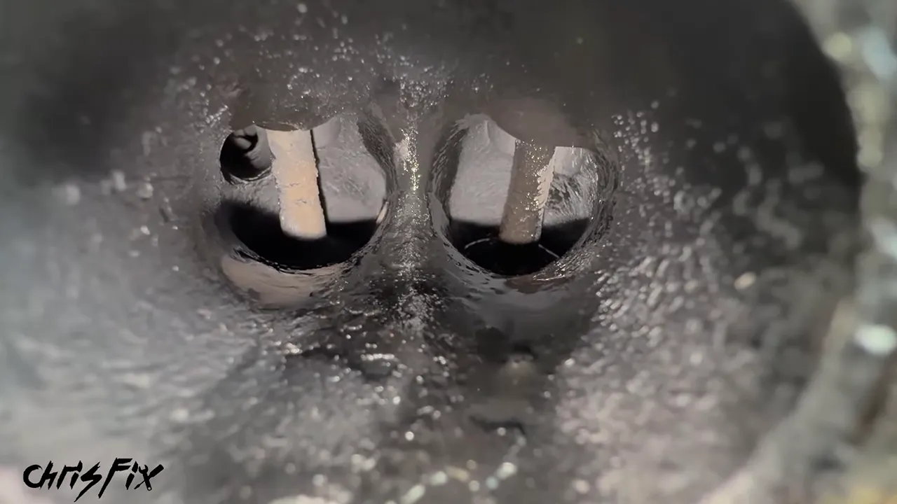
Removing an exhaust manifold can introduce extra work. One of my studs snapped during removal, so don’t treat this inspection as a necessary shortcut. If you remove yours, address damaged hardware and reinstall the manifold using the specified torque and tightening sequence.
Why Burning Oil Can Become an Expensive Problem
Keeping the oil topped off is important, but it does not eliminate the consequences of burning it.
- Low engine oil: Continued oil consumption can bring the level low enough to damage the engine.
- Oxygen sensor contamination: Oily deposits can interfere with the sensor’s readings and fuel control, potentially contributing to poor idle, stalling, misfires, excess fuel consumption, or a check engine light.
- Catalytic converter damage: Oil contamination can reduce the effectiveness of the converter’s fine honeycomb structure, potentially leading to an efficiency code such as P0420 and an emissions failure.
The catalytic converter uses a ceramic honeycomb coated with precious metals to help convert harmful exhaust gases into less harmful products. Coating that working surface with oil residue makes its job harder. Fixing the source of the oil consumption helps protect more than just the engine.
Tools and Parts You’ll Need
Get your tools organized before opening the engine. You don’t want to leave the valvetrain exposed while searching for something.
- Safety glasses and common hand tools, including sockets, ratchets, wrenches, and a flathead screwdriver.
- A torque wrench suitable for the relatively low torque values involved.
- A spark plug socket, labels or tape, an air blower, and a vacuum.
- A compatible screw-down valve spring compressor or another suitable keeper removal and installation tool.
- Quality valve stem seal removal pliers.
- A magnet and tweezers for handling the small valve keepers.
- Replacement valve stem seals with their protective installation sleeves.
- Assembly lube and a deep socket that contacts the new seal’s metal shoulder.
- A feeler gauge for checking valve lash.
- An air compressor and spark plug hole adapter, or clean 1/4-inch rope.
- A leak-down tester if you want to check cylinder sealing while everything is accessible.
- Replacement valve cover gaskets, spark plug well seals, and applicable rocker assembly seals.
- Clean towels and a clean surface for removed parts.
The inexpensive seal removal pliers I initially tried slipped repeatedly. A better pair made a huge difference. Saving money on the repair is great, but a tool that grips properly can save frustration and help prevent damage.
Some major auto parts stores offer loaner specialty tools, although availability and deposit requirements vary. Check before buying a tool you may only use occasionally.
1. Remove the Valve Cover and Expose the Valvetrain
Work with the engine cooled down and wear safety glasses, especially when using compressed air or handling valve springs.
- Label the spark plug wires. I numbered mine one through four so each wire would go back to its original cylinder. Remove the wires.
- Clean before opening anything. Blow loose dirt off the valve cover. Loosen dirt in the spark plug wells with air, then vacuum it out before removing the plugs.
- Remove the spark plugs. Break them loose with the ratchet, then unscrew them the rest of the way by hand.
- Inspect the plugs and wells. One of mine had oil on the ceramic from oil collecting in the well. We’ll repair those well seals during reassembly.
- Remove the valve cover fasteners and cover. Disconnect the vacuum line that needs to come out of the intake to free the cover.
- Remove the upper timing belt cover. On this engine, a 10 mm bolt holds it in place.
With the cover off, the rocker arms, valve springs, and camshaft are exposed. The valve stem seals sit down at the base of the valve springs.
Keep the open engine clean. This is not the time to do other dusty work in the engine bay. Anything that settles on the exposed valvetrain can end up inside the engine.
2. Remove the Rocker Arm Assembly Carefully
This Honda’s rocker arm assembly is held down by 16 bolts. Don’t loosen them randomly. Unevenly releasing the load can distort or damage the assembly.
Use the loosening sequence in your service manual. For this engine, I initially loosened the bolts about a quarter turn each, working from the outside toward the middle:
- The two outer bolts at one end, then the two at the opposite end.
- The top, bottom, and center bolts for cylinder one.
- The top, bottom, and center bolts for cylinder four.
- The corresponding bolts for cylinder two, followed by cylinder three.
Once the load is released, finish unthreading all 16 bolts by hand. Leave the bolts sitting in their original positions in the assembly so they don’t get mixed up.
My assembly was stuck. I carefully lifted at a suitable lip on the end bearing cap, using a folded towel beneath the pry bar to protect the gasket surface. A small movement at each end was enough to free it. Don’t force it or pry against delicate surfaces.
Lift the assembly straight up and set it on a clean work surface.
3. Position the Piston and Block Open Passages
Before removing a valve spring, you need to prevent its valve from dropping into the cylinder.
For the compressed air method, put the piston in the cylinder you’re working on at top dead center. The air holds the valve closed, while the raised piston provides a backup if pressure is lost. With the piston down, a dropped valve could fall far enough that retrieving it requires removing the cylinder head.
Find top dead center without scratching the piston
Insert a long plastic straw or wooden dowel through the spark plug hole so it rests on the piston. It must be long enough to retrieve easily. Don’t use a screwdriver or another metal probe against the piston.
Use a ratchet on the crankshaft pulley bolt to turn the engine by hand in its normal direction. This Honda turns counterclockwise; verify the direction for your engine.
As the crankshaft turns, the straws rise and fall with the pistons. Stop when the piston you need reaches the top of its stroke. On this engine, cylinders one and four rise together, while two and three move together. That allowed me to replace the seals in cylinders one and four before repositioning the engine.
Removing this rocker assembly also removes a bearing cap at one end of the camshaft. I supported that end of the cam while turning the engine so it could not lift. Check your engine’s procedure before rotating anything with valvetrain components removed.
Keep the tiny valve keepers out of the engine
The two small keepers at the top of each valve lock the spring retainer to the valve stem. They are easy to drop.
Block every exposed oil drain passage with clean, retrievable towel pieces. Keep a wide end above the opening so each piece can be removed later. Protect the spark plug wells too, leaving only the cylinder you’re working on accessible.
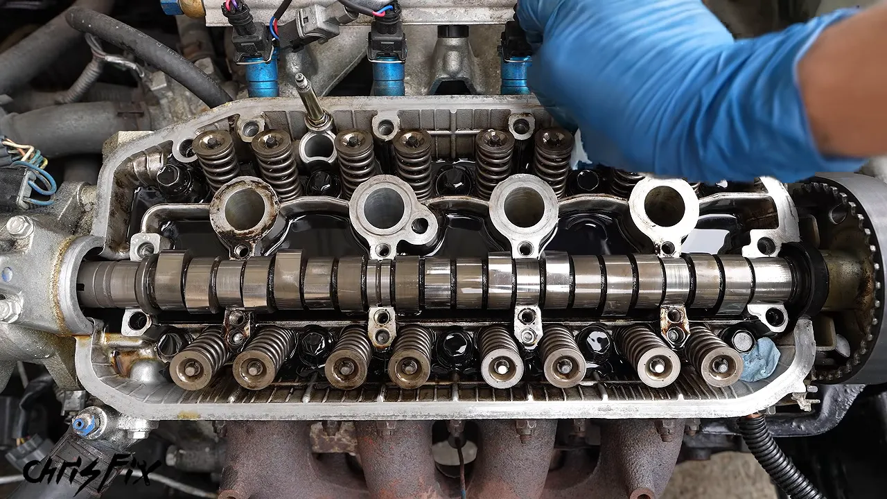
I temporarily hand-threaded the spark plugs into the other cylinders and covered the wells. That added resistance to engine rotation, but it is not a substitute for controlling crankshaft movement when applying compressed air.
Keep track of every towel, sleeve, keeper, and tool. Everything placed in or around an opening must come back out before reassembly.
4. Hold the Valves Closed with Compressed Air
Compressed air is my preferred method because it’s quicker and easier than feeding rope into each cylinder.
- Confirm that the working piston is at top dead center and that the crankshaft cannot move unexpectedly.
- Thread a compatible air adapter into the spark plug hole until snug.
- Connect the air supply.
- Introduce air slowly while monitoring the engine and pressure.
For this repair, I used 75 psi, approximately 5 bar, within a working range of 50 to 100 psi. Follow the requirements of your engine and tools rather than assuming that range applies to every setup.
Opening the air valve abruptly can push the piston down and rotate the engine. Keep clear of the crankshaft tool and moving components, and don’t rely on air pressure alone as your backup against dropping a valve.
A compatible hose from a compression or leak-down tester may provide the adapter you need. Verify that its configuration allows air to flow into the cylinder.
5. Replace Each Valve Stem Seal
Work on one valve at a time. Once you get the process down, it becomes a manageable routine: remove the spring, replace the seal, reinstall the spring, and verify the keepers.
Compress the spring and remove the keepers
- Fit the spring compressor’s hooks beneath the spring coils, keeping the tool clear of the camshaft.
- Tighten the tool gradually until the spring retainer moves down and the keepers become loose.
- Use a magnet to remove both keepers.
- Note their orientation and place them somewhere secure.
- Lift out the spring and compressor together.
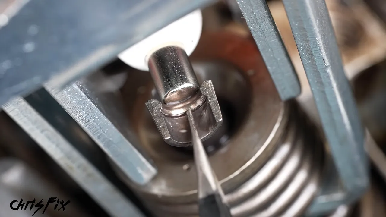
On these keepers, the ridge belongs at the top and the narrower tapered end points down. Pay attention during removal so they go back correctly.
On several old seals, I found the small spring that should surround the seal had come loose. The worst leaking valve also had a damaged-looking seal spring. The rubber itself did not have to be visibly crumbling to leak after more than 200,000 miles.
Remove the old seal without damaging the valve stem
Slide the protective sleeve supplied with the new seals over the valve stem. It helps protect the stem if the pliers slip.
Grip the old seal firmly with seal removal pliers. Wiggle it gently while pulling straight upward until it works loose. If the seal is oily and slippery, wipe it off before trying again.
Don’t lever the pliers against the valve stem or scratch the nearby camshaft. Those polished surfaces need to stay smooth.
Install the new seal using its metal shoulder
- Clean the surface where the new seal will seat.
- Reinstall the protective sleeve over the valve stem. The keeper groove has a sharp edge that can damage the new seal’s lip.
- Slide the new seal down by hand.
- Choose a deep socket that contacts only the seal’s metal shoulder.
- Tap the seal lightly until fully seated, then stop.
- Remove the protective sleeve.
On my seals, an 8 mm socket pressed against the rubber, which could damage it. A 10 mm socket rested on the metal shoulder. Choose by fit, not by copying the socket size.
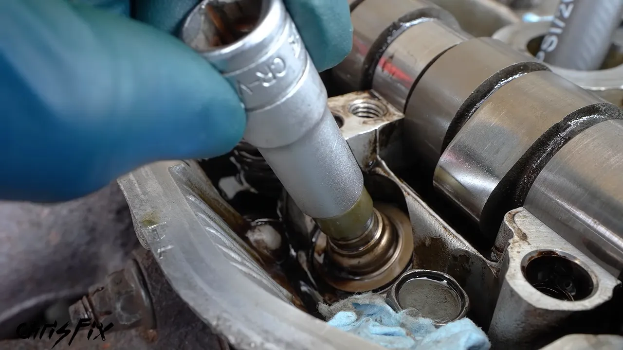
The tapping sound changed pitch when the seal seated. Continuing to hammer after that can deform it and create another leak.
Reinstall the spring and lock both keepers in place
Carefully lower the spring and retainer over the valve stem. Add a small amount of tacky assembly lube near the keeper groove to help the keepers stay in position.
Use tweezers to place both keepers against the stem in the correct orientation. Then slowly release the spring compressor, making sure the retainer rises evenly over both keeper halves.
Remove the tool without hitting the camshaft. Inspect both keepers and check that the retainer is properly locked before moving on. I also press down on the retainer as a final seating check.
Do not disconnect the air or reposition the engine while a valve is missing its spring and keepers.
Other Ways to Remove and Install Valve Keepers
Tool access varies, so I tried several options. The best choice is a compatible tool that you can control comfortably in the available space.
Magnetic keeper remover and installer
A magnetic keeper tool uses downward pressure to compress the spring and capture the keepers inside its magnetic end.
For removal, take off the installation attachment, center the tool over the retainer, and press down. Once the keepers release, the magnet holds them while you lift off the retainer and spring.
For installation, replace the seal, add assembly lube, and position the spring, retainer, and correctly oriented keepers. Fit the tool’s installation end centrally over the keepers and apply a quick downward push. Inspect the keeper seating afterward.
The wrench and sandwich bag method
I also demonstrated an improvised method using a box-end wrench and a sandwich bag. A purpose-built tool is the better first choice, but the trick shows how the retainer and keepers work together.
For removal, I placed a larger box end over the retainer, pressed down, and removed the keepers with a magnet. Then I slowly released the spring pressure. I used a 19 mm wrench for that particular retainer.
For installation, I positioned the spring, retainer, and keepers, laid a sandwich bag over them, and used a smaller 12 mm box end to press down centrally. As the bag stretched, it helped keep the keeper halves against the valve stem until the retainer captured them.
This requires control of a spring under load. Keep your safety glasses on, release pressure carefully, remove the bag completely, and verify both keepers. If the fit or access is poor, use the proper tool instead.
6. Use Rope If You Don’t Have an Air Compressor
The rope method supports the valves mechanically. Instead of holding them shut with air, you pack clean rope into the cylinder and bring the piston up until the rope presses against the valves.
I used compressed air for cylinders one and four, then rope for cylinders two and three.
- Start with the piston lowered and the valves closed. This gives the rope room to enter the cylinder.
- Feed in clean 1/4-inch rope. Inspect it for dirt, loose fibers, and a frayed end. Leave a generous tail outside the spark plug hole.
- Turn the crankshaft slowly by hand. Bring the piston upward until the rope packs against the valves and resistance increases.
- Stop at firm resistance. Don’t force the crankshaft.
- Protect the openings again. Block the surrounding wells so keepers cannot fall inside.
- Replace the seals. Follow the same spring, seal, and keeper procedure used with compressed air.
- Relieve pressure and remove all the rope. Only do this after every spring and both keepers are securely installed.
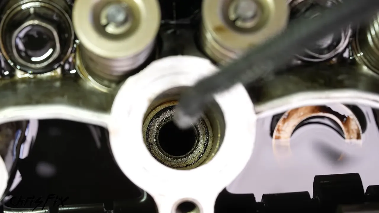
It took about 5 feet, or 1.5 meters, of 1/4-inch rope to fill one cylinder of this 1.5-liter engine. That is a useful reference for this engine, not a fixed amount for every cylinder.
To release the rope, I gently rotated this engine backward to lower the piston. Reverse rotation is not appropriate for every timing system, so check your service procedure first. Don’t force the engine, and don’t let the timing belt or chain jump teeth.
The rope method worked, but feeding that much rope through a spark plug hole takes patience. If both options are available, I’d choose compressed air.
At a comfortable pace, the seal replacement itself took me roughly four minutes per valve, a little over 15 minutes per four-valve cylinder. That does not include access, testing, adjustment, or reassembly, and your first attempt may take longer.
7. Check Cylinder Health with a Leak-Down Test
With all 16 seals replaced and the rocker assembly still removed, every valve is closed. That makes this a convenient opportunity to check how well the cylinders hold pressure.
A leak-down tester measures the percentage of supplied air that escapes from the cylinder. Leakage can occur past the valve seats, piston rings, head gasket, or damaged engine components. It checks cylinder sealing, rather than directly testing the valve stem seals.
- Remove all temporary towels and ensure the rope is completely out.
- Follow the tester’s setup and calibration instructions.
- Position and secure the crankshaft as required so air pressure cannot rotate it unexpectedly.
- Thread the adapter into the spark plug hole and connect the tester.
- Apply the specified test pressure slowly and record the leakage percentage.
- Repeat consistently for each cylinder.
My tester used a 100 psi test pressure, with compressor supply pressure above that. Focus on the actual percentage scale, not just broad colored labels.
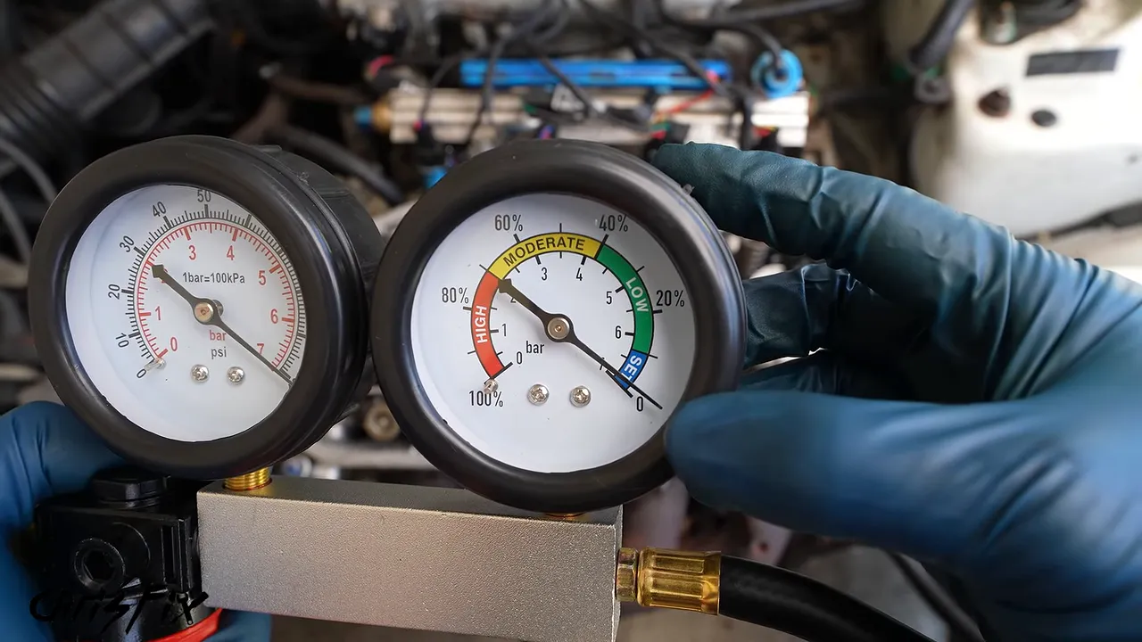
For this check, I was looking for less than 10 percent leakage, with readings around 15 percent or higher warranting investigation. Interpret your results using the tester instructions and engine specifications rather than treating those numbers as universal limits.
Here’s what this engine measured:
- Cylinder one: approximately 3 percent.
- Cylinder two: approximately 5 percent.
- Cylinder three: approximately 5 percent.
- Cylinder four: less than 5 percent.
Beautiful. Those were low, consistent readings for an engine with over 200,000 miles.
8. Replace the Rocker Assembly Seals and Reinstall It
Remove trapped oil from the bolt holes
Some of the rocker assembly bolt holes and locating holes had filled with oil. These holes do not drain.
Wick the oil out before installing the assembly. Trapped liquid can prevent a bolt from seating correctly and create hydraulic pressure as it tightens. Get the holes as dry as practical without leaving debris behind.
Fix the oil in the spark plug wells
Remember the oil on the outside of the spark plug? The seals beneath the rocker assembly were flattened, brittle, and split. One damaged seal was next to an oil feed passage.
Carefully place the rocker assembly on its side without letting its bolts fall out. Remove the old seals, clean their grooves, and press the replacements fully into place. Check that they stay seated before lowering the assembly.
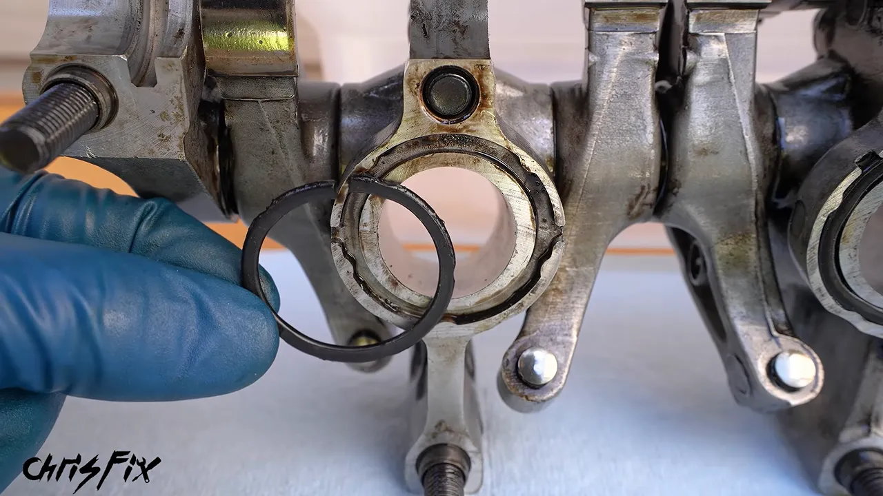
The Honda-specific parts listed for this repair were:
- Round rocker assembly seals: 91301-PJ7-000.
- Figure-eight rocker assembly seal: 91302-PJ7-003.
Verify fitment for your exact engine before ordering.
Lubricate and tighten in the correct sequence
Lubricate the camshaft contact surfaces and all 16 valve stem tips with assembly lube or the lubricant specified for your engine. Clean any drips from the gasket surface, then lower the rocker assembly straight into place.
Start every bolt by hand to avoid cross-threading the aluminum head. Tighten using the service manual’s sequence, which works from the middle outward on this engine.
Rocker assembly bolt torque for this engine: 16 ft-lb, or 22 N·m.
9. Check and Adjust Valve Lash
After torquing the rocker assembly, turn the engine through a couple of rotations by hand in its normal direction. It should move smoothly. Stop if anything binds.
Next, position cylinder one at top dead center on its compression stroke using the timing marks. On this Honda, the cam pulley’s “UP” marking faces upward at the correct starting position.
Valve lash is the clearance between the rocker arm and the top of the valve stem. Use a feeler gauge to measure it with the valve closed and the rocker unloaded. Follow your manual’s temperature requirements for the check.
Valve clearance specifications for this Honda
- Exhaust: 0.009 to 0.011 inch. I used a 0.010-inch gauge.
- Intake: 0.007 to 0.009 inch. I used a 0.008-inch gauge.
Slide the gauge between the rocker and valve tip. You want light, consistent drag. The gauge should move smoothly, but it should not feel completely loose or become trapped.
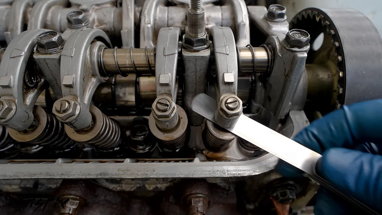
Adjust a clearance that is too tight or too loose
- Loosen the adjuster’s jam nut.
- Place the correct feeler gauge in the gap.
- Turn the adjustment screw with a flathead screwdriver until the gauge has light drag.
- Hold the screw stationary while tightening the jam nut.
- Recheck the clearance after tightening.
Adjuster jam nut torque for this engine: 10 ft-lb.
Rechecking matters because tightening the nut can rotate the screw and change the clearance. On cylinder three, one exhaust valve was too tight for the gauge to enter, while the other was much too loose. Both needed adjustment.
Follow the firing order
This engine’s firing order is 1, 3, 4, 2. After checking cylinder one, I advanced to each cylinder’s specified timing mark in that order.
Each step here is 90 degrees of camshaft rotation, equivalent to 180 degrees at the crankshaft. Confirm the timing mark and make sure the relevant rocker arms are unloaded before measuring. Use your engine’s specified method rather than assuming this sequence applies to every valvetrain.
Check both intake and both exhaust valves on every cylinder. Once all clearances are within specification, the adjustment is complete.
10. Reassemble the Engine and Check the Repair
Remove the ratchet from the crankshaft before starting the engine. It’s an easy thing to overlook after turning the engine by hand throughout the repair.
- Reinstall the upper timing belt cover and its fastener.
- Remove the old valve cover perimeter gasket and clean its channel.
- Press the new gasket fully into the channel.
- Replace the valve cover’s spark plug well seals and fastener seals.
- Lower the valve cover straight down, keeping every seal in position.
- Start the cover nuts by hand and tighten evenly to specification.
- Hand-thread the spark plugs, then torque them to specification.
- Reconnect the labeled plug wires and remove the labels.
- Reconnect the vacuum line to the intake.
For this Honda, the final torque values were:
- Valve cover nuts: approximately 8 ft-lb.
- Spark plugs: 13 ft-lb.
I installed these coated spark plugs without anti-seize. Follow your plug manufacturer’s instructions, since thread treatments affect tightening behavior. NGK’s spark plug installation guidance provides additional context on coated threads and anti-seize.
Before starting, account for every tool, protective sleeve, towel, and length of rope. Confirm that all springs and keepers are installed, the oil level is correct, and everything disconnected during the repair is back in place.
What to expect on the first startup
Moment of truth. Mine started immediately, ran smoothly, and did not produce the original puff of smoke. The valvetrain also sounded quiet after the lash adjustment. That’s the sound of a job well done, and about $2,000 staying in the budget.
If yours smokes briefly on the first start, some residual oil may still need to burn off. Provided the engine is running normally and there are no leaks or warning signs, take a drive, let it sit overnight, and check the next cold start.
The real test is whether the startup smoke stays gone. A successful repair stops oil getting past the valve stem seals, leaves the valve clearances within specification, and keeps the engine sealed up without new leaks. Take your time with cleanliness, valve support, keeper seating, and torque sequences, and those small replacement seals can make a big difference.


