A properly installed battery kill switch does more than disconnect the battery. On a track car, it needs to shut down the engine and stop the electrical system from staying alive on alternator power. If you have an accident, a fuel leak, or an electrical short, one accessible switch gives you a way to shut things down quickly.
That matters especially during a fire. Stopping the engine and fuel pump helps prevent the pump from continuing to feed a fuel leak.
I’m installing a multipole battery cut-off switch in a BMW race car, including new battery cables, an ECU shutdown circuit, an alternator protection resistor, and a custom aluminum mounting panel. Along the way, I’ll show you how to prepare and crimp thick battery cable using three different tools. Getting those connections right is just as important as wiring the switch correctly.
This is a vehicle-specific installation, not a universal wiring diagram. Confirm your vehicle’s wiring, your switch manufacturer’s instructions, and your racing organization’s current requirements before cutting anything. Cable size, switch ratings, auxiliary contact arrangements, and resistor installation must suit your application.
What You'll Learn
- A running engine may stay powered by the alternator after the battery is disconnected.
- This multipole switch combines battery isolation, ECU relay interruption, and an alternator protection resistor circuit.
- Proper cable preparation and test crimps help verify connections before final installation.
- Accessible mounting, protected terminals, secured wiring, and a shutdown test complete the installation.
Table of Contents
- What a Battery Kill Switch Can and Cannot Do
- Choose the Switch Location and Gather Your Supplies
- Disconnect the Battery and Plan the Wiring
- Understand How the Multipole Kill Switch Works
- Measure and Route the New Battery Cables
- How to Prepare Battery Cable for Crimping
- Three Ways to Crimp Battery Cables
- Seal the Terminals and Add Protective Loom
- Install and Connect the Main Cables
- Secure the Wiring, Not Just the Connections
- Wire the ECU Shutdown Circuit
- Connect the Alternator Protection Resistor
- Fabricate a Custom Kill Switch Mounting Panel
- Install the Panel and Protect the Positive Studs
- Test That the Switch Stops the Engine and Electrical Power
What a Battery Kill Switch Can and Cannot Do
A track car is the main application here, but a battery disconnect can also be useful in a couple of other situations:
- Battery drain while parked: Disconnecting the battery prevents vehicle circuits downstream of the switch from drawing power.
- Theft deterrence: A switch with a removable handle can interrupt the power needed to start the car.
- Emergency shutdown: A correctly wired racing installation disconnects battery power and stops the engine, even while the alternator is generating electricity.
If your battery keeps going dead, finding and repairing the parasitic draw is still the proper fix. A disconnect is a workaround, not a diagnosis. My parasitic draw test explains how to track down that problem.
Also remember that disconnecting battery power can reset the radio, computer memory, and other settings. That is worth considering before adding one to a street car.
Choose the Switch Location and Gather Your Supplies
Make it reachable in an emergency
For this race, a track worker needs to reach the kill switch from outside the car. The driver also needs to operate it while fully strapped into the harness.
The opening on the left side of this BMW’s dashboard meets both needs. It has room for a mounting panel, it is accessible through the driver’s window, and it is within reach from the seat. A location in the middle of the cabin would not work nearly as well.
Check your own rulebook before committing to a location. Requirements vary, and organizations such as SCCA publish their competition rules for reference.
Tools and electrical supplies
Most of this job uses ordinary hand tools. The bracket requires some basic fabrication tools, and the battery cables require a crimper designed for heavy cable.
- A suitable multipole battery kill switch with its specified alternator protection resistor.
- Battery cable sized for the vehicle and added cable length. I used 2 AWG cable for this installation.
- Matching ring terminals, heavy-duty butt connectors, and female blade connectors.
- Smaller wire for the relay interruption and resistor circuits, sized to suit those circuits.
- Heat-shrink tubing, split wire loom, electrical tape, and cable identification tape.
- Cable cutters, a stripping tool or sharp razor, and a small-wire crimper.
- A hammer, hand, or hydraulic battery cable crimper. You only need one appropriate tool.
- A multimeter with a continuity setting.
- Ratchets, sockets, wrenches, screwdrivers, a file, and safety glasses.
- A drill, drill bits, a step bit, and a center punch.
- A jigsaw with a metal-cutting blade, aluminum sheet, cardstock, and mounting hardware.
- 180-grit and 320-grit sandpaper, cleaning alcohol, and suitable paint.
- A heat gun, preferably with a wraparound heat-shrink attachment.
Ryobi supplied tools for this project. Their shared 18-volt battery system is convenient for a home setup, but you do not need a particular brand to do this job. I originally planned to cut the panel with an angle grinder and cut-off wheel, then switched to a jigsaw because it made the panel’s shape easier to cut accurately.
Disconnect the Battery and Plan the Wiring
Disconnect the battery’s negative cable before working on the wiring. On this BMW, the battery is in the trunk, and the terminal clamp takes a 10 mm socket. Move the disconnected cable away from the battery post so it cannot accidentally reconnect.
The kill switch itself goes into the positive side of this installation. That is required for this race setup, and the complete wiring arrangement also needs to deal with alternator power and engine shutdown.
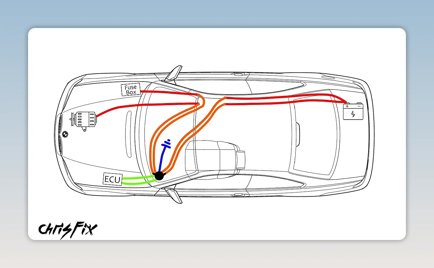
This car has two positive cables running forward from the trunk along the passenger-side sill:
- One feeds the starter and alternator connection through the firewall.
- The other feeds the fuse box.
Both paths need to be accounted for. Interrupting only one would leave an incomplete shutdown arrangement.
Before cutting a cable, draw your wiring plan. Mine includes four heavy cables running to the switch, two smaller wires interrupting the ECU relay circuit, and a resistor circuit connected to chassis ground.
Understand How the Multipole Kill Switch Works
The switch used here has two large main studs and four smaller terminals arranged as two auxiliary circuits. The terminal numbers below apply to this particular switch. Do not assume another switch uses the same labels or internal connections.
The main studs disconnect the battery
The two battery-side cables connect to one large stud. The alternator/starter feed and fuse-box feed connect to the other large stud.
With the switch on, the studs are electrically connected. With it off, the connection opens and isolates the battery from those vehicle circuits.
Here is the important part: disconnecting the battery alone may not stop a running engine. The alternator can continue supplying enough electricity to keep the engine and electrical system operating.
Circuit 2 stops the engine
The terminals marked “2” are connected with the switch on and disconnected with it off. They can interrupt an appropriate ignition or engine-control circuit.
On this BMW, I’m using them to interrupt the low-current trigger circuit for the ECU main relay. Opening that circuit switches off the relay, removes the ECU’s operating power, and stops the engine.
Circuit 1 provides the resistor path
The engine and alternator do not stop rotating the instant the switch opens. The alternator can still generate electricity during that brief rundown, so this switch uses a resistor path to help protect against the resulting voltage transient.
The connections are:
- A jumper runs from the large alternator and fuse-box stud to one terminal marked “1.”
- The other terminal marked “1” connects through the specified resistor to chassis ground.
- When the switch is turned off, that auxiliary circuit closes and provides a load through the resistor.
The resistor is essential. Do not connect that terminal directly to ground without it. Use the resistor and installation method specified for your switch, including its mounting, insulation, and heat-clearance requirements.
A continuity test helps you understand the switch before installation. With the switch disconnected from power, check which contacts close in each position. The meter’s beep indicates continuity, not that the switch has been proven capable of carrying its operating load.
Measure and Route the New Battery Cables
I chose to interrupt the original positive cables near the front passenger footwell. That keeps the connections away from the planned fire suppression equipment and provides a practical route up through the center console and behind the dashboard.
- Cut the original cables squarely. Use large cable cutters that can make one clean cut instead of hacking through the strands with undersized cutters.
- Route one new cable as a trial. Run it from the connection area, up through the console, behind the instrument cluster, and over to the switch location.
- Check clearance. Refit the cluster and make sure it does not press against the cable.
- Leave some working length. A little extra is better than a cable pulled tight. Trim it after confirming the final route.
- Use the trial cable to measure the others. This installation needs four heavy cables between the original connections and the switch.
During the trial routing, I found that one new cable could connect directly to the existing firewall stud. That is cleaner than adding an unnecessary splice to the short original section.
All four cables will receive protective loom. Plan for that extra bulk now, because four lengths of 2 AWG cable take up a surprising amount of space behind the dash.
How to Prepare Battery Cable for Crimping
A strong battery cable connection starts before you squeeze the crimper. The lug must match the cable, the stripped length must be correct, and every copper strand needs to fit inside the barrel.
Select the correct terminal
A lug marked “2 × 3/8” identifies two separate sizes:
- 2: The terminal accepts 2 AWG cable.
- 3/8: The ring fits a 3/8-inch stud.
Match both dimensions to the job. A ring that fits the stud does not necessarily have the correct barrel for the cable.
Strip the insulation without damaging the copper
Hold the terminal alongside the cable to establish the required strip length. If using a razor, carefully score only the insulation around the cable, then make a lengthwise slit so the insulation can peel away. Do not saw into the copper strands.
Those strands provide the cable’s current-carrying cross-section. Cutting some away reduces the amount of copper available to carry the load.
- Start with a straight, square cable end.
- Remove enough insulation for the conductor to fill the terminal barrel.
- Slide the heat-shrink tubing onto the cable before fitting the terminal.
- Gently pinch and twist the strands together.
- Push and slightly twist the terminal onto the cable until it is fully seated.
- Check that no strands have folded back or escaped outside the barrel.
I always emphasize the heat shrink because it is easy to forget. Once the ring terminal is installed, tubing sized closely to the cable may not slide over it.
Three Ways to Crimp Battery Cables
All three crimpers can make a good connection with compatible cable and terminals. Their differences are cost, effort, access, and how easy they are to use inside the car.
Hammer crimper: inexpensive, but it needs a solid base
A hammer crimper supports the lug while a driven punch compresses the barrel. Position the barrel in the tool and strike it according to the tool’s instructions. I used a 4-pound hammer for the demonstration.
This is the least expensive option of the three, but it needs a firm foundation and room to swing. A flexible floorboard is not a suitable hammering surface, so it is not practical for the connections that must be made inside this car.
Hand crimper: a practical middle ground
The long-handled cable crimper uses leverage and selectable dies to compress the terminal. The tool demonstrated covers 8 AWG through 0 AWG cable.
Its dies are relatively narrow, so I made two adjacent compressions along the barrel. Bracing one handle against a stable surface made it easier to hold the cable in position while closing the tool.
This is a useful balance of price and capability, especially when you need to work in the car rather than at a bench.
Hydraulic crimper: less effort, but verify the result
A hydraulic cable crimper uses a pump handle to close its dies. The wider dies on this tool compress a larger section of the barrel in one operation, and the hydraulic action makes it much easier to squeeze thick terminals.
However, the first test crimp was not as compressed as it needed to be. After changing the die setup, the second sample had a much denser cross-section.
That is why I do not judge a crimp only by how nice it looks from the outside. Use the tool and terminal manufacturer’s compatible die selection, then verify the result rather than relying on a size marking alone.
Test your crimp before committing to the whole job
Give every completed connection a firm pull test. The terminal should not move on the cable.
For a new tool, cable, or terminal combination, make a sacrificial sample and cut it through the compressed area. In these demonstrations, the good samples showed tightly compacted copper with no obvious internal voids. The poor sample showed distinct loose strands and air gaps.
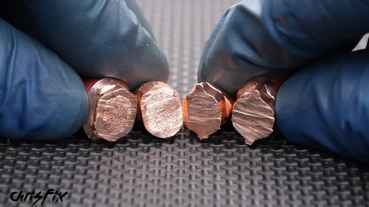
A pull test checks mechanical retention. Inspecting a test sample gives you another useful check of the crimping setup. Do that before producing all of your finished cables.
Seal the Terminals and Add Protective Loom
After crimping the four switch-end terminals, inspect them for sharp burrs. Lightly file those burrs smooth so they cannot cut into the heat shrink as it contracts.
I added a small amount of silicone paste at the junction between the terminal barrel and cable insulation, then positioned the heat shrink over that joint. Keep the electrical contact faces clean, and use sealing materials compatible with your tubing and terminals.
The heat gun’s wraparound attachment heats the tubing from multiple sides, making it easy to shrink evenly without constantly rotating the cable.
A simple trick for installing split wire loom
Pushing thick cable into tight split tubing by hand gets tedious fast. A box-end wrench makes a handy guide:
- Slide the closed end of the wrench over the cable from the unterminated end.
- Position the wrench in the loom’s split.
- Move it along the cable so it opens the split and guides the cable inside.
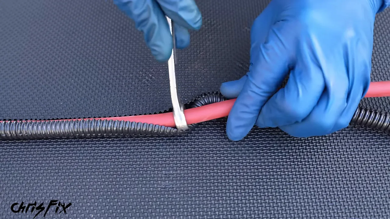
This works most easily with a little extra space inside the loom, but it still helps with a snug fit.
Install and Connect the Main Cables
Label everything before hiding it behind the dash
Four identical cables become difficult to identify once they disappear behind the instrument cluster. I marked the alternator and fuse-box cables with yellow tape and left the battery-side cable ends unmarked.
Label both ends consistently. It takes seconds now and avoids tracing hidden cables with a multimeter later.
Connect the switch end
Route the protected cables through the console and behind the cluster, working two at a time where space is tight. Refit the cluster again to confirm clearance.
- Put both battery-side ring terminals on one large switch stud.
- Put the alternator/starter-feed and fuse-box ring terminals on the other large stud.
- Add the resistor-circuit jumper to that same alternator and fuse-box stud.
- Fit the specified washers and nuts, leaving them hand-tight while positioning the switch.
The heavy cables are stiff. Allowing the terminals to rotate slightly during fitting makes the switch much easier to position. They must receive their final tightening before the battery is reconnected.
Connect the vehicle end
The alternator/starter-feed cable gets a ring terminal and connects directly to the firewall stud. After tightening the connection, reinstall its protective plastic cover.
The remaining connections use appropriately sized heavy-duty butt connectors:
- Insert the first stripped cable end to the connector’s midpoint and crimp it.
- Slide the heat shrink onto the cable before joining the second side.
- Insert and crimp the second cable end.
- Check the connection with a pull test.
- Seal and insulate the joint, then restore the protective loom.
Repeat for the fuse-box feed and both battery-side connections. Be deliberate about matching each cable to the wiring plan.
Secure the Wiring, Not Just the Connections
At this point, the cables are connected, but loose wiring across the floor is not a finished job. Cable management protects the insulation, reduces movement, and keeps the wiring away from places where it could be damaged.
I used two types of mounts:
- Adhesive zip-tie mounts: Clean the painted surface with alcohol, let it dry, and press the mount firmly into place before securing the cable.
- Push-in mounting zip ties: These use an existing hole in the sheet metal to anchor the cable bundle.
The single firewall cable follows its own route. Three other cables fit inside a larger, approximately 1-inch loom before being secured together. Trim the zip-tie tails and check that nothing interferes with the pedals, seat, or nearby equipment.
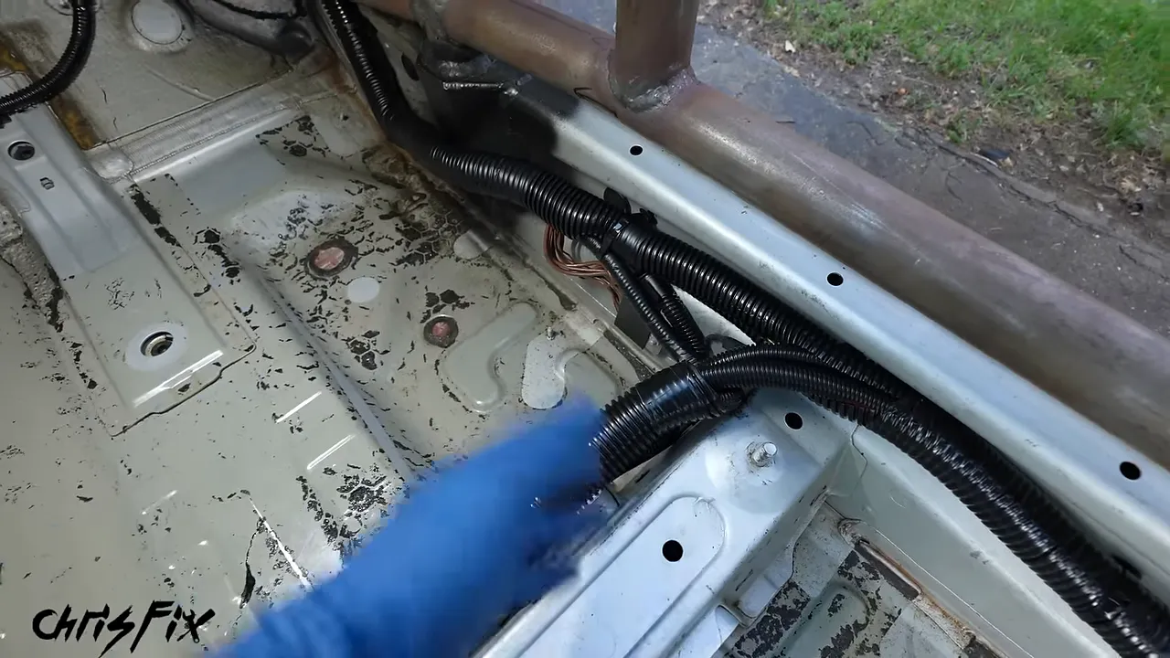
Follow the full route behind the dashboard and along the sill, too. Loom is extra abrasion protection, not a substitute for keeping cables away from sharp edges and securing them properly.
Wire the ECU Shutdown Circuit
BMW calls its engine computer the DME. On this car, it sits beneath a plastic cover in the engine compartment, alongside the relay that supplies it with power.
The goal is to interrupt the relay’s low-current control circuit, not send the computer’s main operating current through an unsuitable auxiliary contact.
Identify the correct relay and wire
I used a relay-box diagram to locate the ECU main relay, which is blue on this particular car. Removing the ECU connectors and lifting the relay bracket provided access to the wiring beneath it.
The relay has several thick power wires and a thinner trigger wire. The thin wire was the intended interruption point, but wire thickness and relay color alone are not enough to identify a circuit. Confirm the function using the correct vehicle wiring information.
Before permanently cutting it, I verified the circuit by disconnecting the identified control connection with the engine running. The engine stopped immediately.
That temporary test requires particular care. All ECU connections must first be restored, the new main connections must be secure, and exposed positive terminals must be protected from grounded metal before reconnecting battery power. Disconnect the battery again before making the permanent wiring changes.
Extend both sides of the interrupted wire to the switch
- Reconnect the tested relay connection securely.
- With the battery disconnected, cut and strip the identified trigger wire.
- Crimp an extension wire onto each cut end using suitable butt connectors.
- Pull-test and heat-shrink both connections.
- Secure the extensions to the surrounding harness so the splices do not carry tension.
- Route both wires into the cabin through a protected passage.
- Crimp insulated female blade connections onto the switch ends.
- Connect one wire to each terminal marked “2” on this switch.
For this simple series interruption, either extension can go to either terminal in that pair. What matters is that the circuit is complete with the switch on and interrupted with it off.
Protect the extensions with loom, especially around the firewall and dashboard. A chafed control wire could shut off the engine unexpectedly.
Connect the Alternator Protection Resistor
Connect the jumper from the alternator and fuse-box main stud to one terminal marked “1.” The other “1” terminal connects through the supplied resistor to a clean chassis ground.
I built that lead by crimping a wire to each end of the resistor, insulating the connections, and adding a ring terminal at the chassis end. The ground point is a bolt into substantial bare chassis metal, providing a clean electrical connection.
Follow the resistor manufacturer’s thermal instructions. A resistor dissipates energy as heat, so do not assume every resistor can be enclosed in heat shrink or loom. Its body mounting and clearances need to follow its own specifications.
Once the auxiliary circuits are complete, reinstall the relay bracket, reconnect every ECU plug fully, and refit the enclosure cover. On this BMW, the connectors have distinct shapes, but each still needs to be fully seated and latched.
Fabricate a Custom Kill Switch Mounting Panel
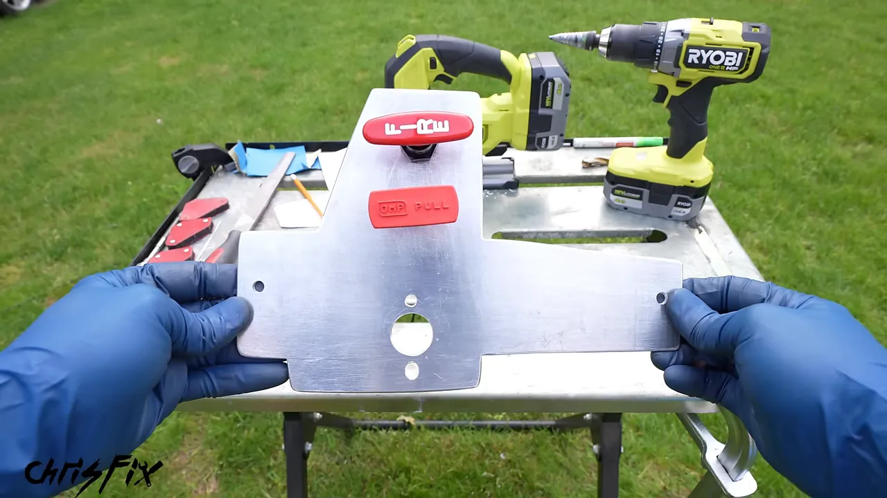
The electrical work is complete, but the switch still needs a rigid mount. A custom panel also leaves space above it for the two fire suppression pull handles planned for this car.
Make a cardstock template
Cardstock is flexible enough to trace the dashboard opening but stiff enough to hold its shape. Cut the template, test-fit it, and adjust it before transferring the outline to aluminum.
I used approximately 1/8-inch aluminum sheet. Trace the template with a thick marker so the cutting line is easy to follow.
Cut, file, and smooth the panel
Clamp the sheet securely and cut it with a jigsaw fitted with an appropriate metal-cutting blade. The jigsaw makes the changes in direction much easier than a cut-off wheel.
Test-fit the panel, then use a metal file to round the corners and remove small amounts where needed. Keep checking the fit rather than removing too much material at once.
Next, wrap 180-grit sandpaper around the edges and work it back and forth. This removes sharpness and gives the panel a much more finished appearance.
Transfer the dashboard mounting holes
This dashboard has two existing mounting points that work well for the panel. To transfer their locations:
- Hold the cardstock template in its final position.
- Press it against each mounting hole using the rounded end of a screwdriver.
- Transfer the template to the aluminum.
- Center-punch and drill the marked locations.
- Test-fit both bolts to make sure they thread in straight.
Drill the switch and accessory holes
The switch used here needs a 7/8-inch center opening plus two smaller mounting holes. Make a separate cardstock pattern for the switch, choose its position on the panel, and center-punch all three hole locations.
A step bit works well for the large opening. I marked the 7/8-inch step with a bright green marker so the target size was easy to identify while drilling. Stop when that step has completed the hole.
Mark all the smaller hole centers before drilling destroys the paper template. Deburr the holes and test-fit the switch.
I also drilled the two fire suppression handle openings above it, positioning the lower handle so it would not obstruct the kill switch. Those openings need to match the particular pull-handle hardware.
Prepare and paint the panel
Remove the hardware and sand the face with 320-grit paper. Scratches that remain now can still show after painting, so take a little time to get the surface smooth.
Wipe away dust and oils with 90 percent alcohol and let the panel dry. I used a paint designed to bond directly to metal without primer, applied two coats, and left it overnight. Follow the preparation, recoat, and curing directions for your chosen paint.
Install the Panel and Protect the Positive Studs
Start the panel bolts by hand so they do not cross-thread, then secure the panel to the dashboard. Fit the kill switch and tighten its mounting hardware until snug.
Do not overtighten the switch’s plastic body. Cracking the housing would undo all that careful work.
Install any adjacent pull handles and make sure their hardware is secure. Then tighten the two large electrical stud connections according to the switch manufacturer’s instructions. This is the final tightening that was deliberately left until the switch and stiff cables were in position.
Add insulating boots over both positive studs. Those covers help prevent a tool or other grounded object from touching an exposed terminal and creating a short.
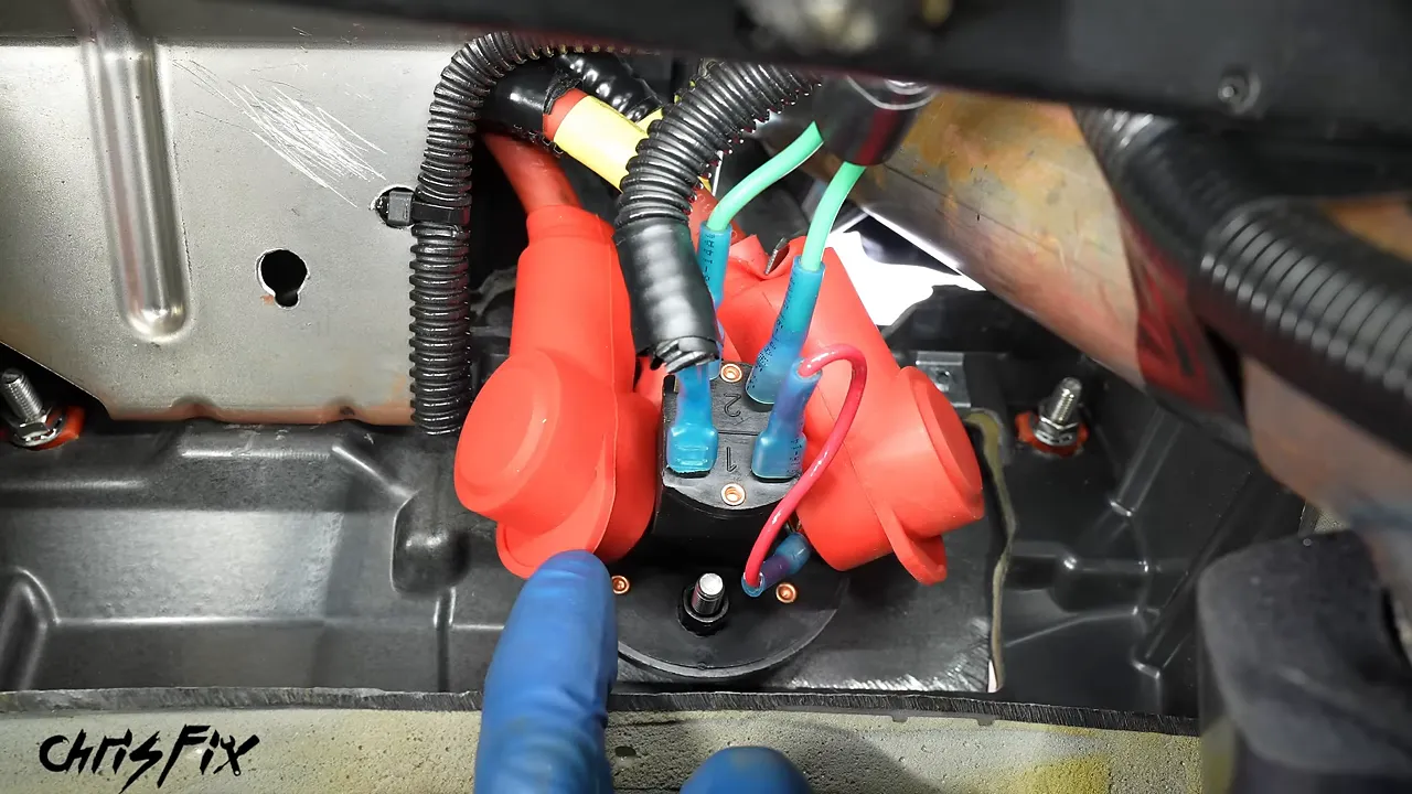
Before reconnecting the battery, check the cable routing, terminal tightness, auxiliary connections, ground, and resistor installation one more time. Reconnect and tighten the negative battery terminal only when everything is ready for testing.
Test That the Switch Stops the Engine and Electrical Power
A switch that disconnects the battery but leaves the engine running has not achieved the goal. The final test needs to confirm the whole system works together.
- Turn the kill switch on. Confirm that normal electrical power returns.
- Start the engine. Let it idle and make sure it runs normally.
- Check engine response. Confirm there is no obvious running problem after the wiring changes.
- Perform the required shutdown test safely. For this race’s inspection, the engine must be held above 3,000 rpm while the inspector turns the switch off.
- Confirm a prompt shutdown. The engine should stop quickly and the switched electrical system should lose power.
On this car, switching it off above 3,000 rpm stopped the engine immediately and removed electrical power as intended. Use your own event’s procedure rather than assuming that exact test applies everywhere.
Finally, add the required kill-switch identification sticker where track workers can clearly see it. An emergency switch needs to be easy to recognize as well as easy to reach.
The finished installation is more than a red handle in the dashboard. It is a complete system: battery isolation, reliable engine shutdown, alternator protection, solid cable crimps, protected wiring, and a secure mounting panel. Take the time to get each part right, and the result is a clean, professional installation that does its job when you need it.


