Converting a compatible car to flex fuel comes down to three main jobs: install an ethanol sensor in the fuel line, connect a wiring harness between the factory harness and the fuel injectors, and plug everything into a piggyback computer. That computer adjusts injector operation for the ethanol content in the fuel.
The result is flexibility. You can use normal gasoline, E85, or a mixture of the two without draining the tank every time you switch fuels.
I'm installing an eFlexFuel eFlexPlus kit on a four-cylinder Toyota Prius. The basic process applies to other compatible vehicles, but fuel fittings, injector connectors, access, and torque specifications will vary. Use the instructions for your exact kit and the service information for your vehicle alongside this guide.
What You'll Learn
- Confirm vehicle compatibility before installing an ethanol sensor, injector harness, and piggyback computer.
- Match fuel fittings carefully and route hoses away from heat, rubbing, and tight bends.
- Verify injector polarity before assembling connectors, keeping each factory lead paired with its corresponding injector.
- Check every fuel connection for leaks and verify sensor and injector operation before adding E85.
Table of Contents
- Why Convert a Car to E85?
- Check Compatibility and Gather Your Tools
- 1. Prepare the Car and Relieve Fuel Pressure
- 2. Create Access to the Fuel Line
- 3. Plan the Ethanol Sensor and Fuel Hose Routing
- 4. Assemble and Install the Fuel Hoses
- 5. Identify Injector Polarity and Assemble the Harness
- 6. Route the Harness and Connect the Computer
- 7. Start the Engine and Check for Leaks
- 8. Reassemble the Cowl and Secure the Computer
- 9. Add E85 and Confirm the Blend
Why Convert a Car to E85?
Lower fuel prices, with a fuel economy tradeoff
E85 can cost considerably less per gallon than gasoline. At two stations I checked, premium gasoline was about $6.30 versus $3.30 for E85, and $4.40 versus $2.60 for E85. Those are examples of local prices at the time, not prices you should expect everywhere.
There is a catch: expect roughly 15 to 25 percent lower fuel economy, depending on the car and fuel blend. A cheaper gallon does not automatically mean cheaper driving. Compare the price difference against the reduction in miles per gallon, and compare E85 with the gasoline grade your car actually requires.
More performance potential in the right engine
E85's high octane makes it especially useful for turbocharged, supercharged, and high-compression engines. With appropriate tuning, that knock resistance can allow the engine to run more boost and make more power.
For example, my buddy's Supra made 454 horsepower on 93-octane gasoline. After switching to E85 and increasing boost, it made 672 horsepower. That's a huge difference, but the important detail is that the boost and tuning changed too. Installing a conversion kit alone does not promise that kind of horsepower increase.
Emissions and storage considerations
Ethanol blends can reduce certain pollutants, including carbon monoxide, benzene, and some particulates. The overall emissions picture depends on the vehicle and operating conditions, so it is not as simple as saying every pollutant always decreases. The U.S. Department of Energy's ethanol benefits and considerations provides useful background.
Ethanol also absorbs water. My practical advice is to use the fuel regularly rather than leave E85 sitting in the tank for more than about six months. Fuel availability matters too. I did not have a convenient local E85 pump for this project, so I used purchased cans of E85 for testing.
Check Compatibility and Gather Your Tools
Before buying anything, enter your vehicle's make, year, model, and engine in the kit manufacturer's compatibility checker. If the vehicle is not listed as compatible, do not assume a similar-looking kit will work.
Compatibility is important because the conversion involves more than adding a sensor. The fuel system and injector setup must be suitable for the application.
What's in the conversion kit?
The eFlexPlus kit I'm using includes:
- A piggyback computer that connects to the main harness.
- An ethanol sensor installed inline with the fuel supply.
- A temperature probe that helps the computer distinguish hot and cold starts.
- A ground lead.
- Injector harness branches and connector housings.
- Fuel hose, adapters, and fuel-injection hose clamps.
- A bypass plug for use with normal gasoline if the conversion computer needs to be removed from the circuit.
The kit includes more fittings than this installation needs. Lay everything out first so you understand which parts connect to the vehicle and which connect to the ethanol sensor.
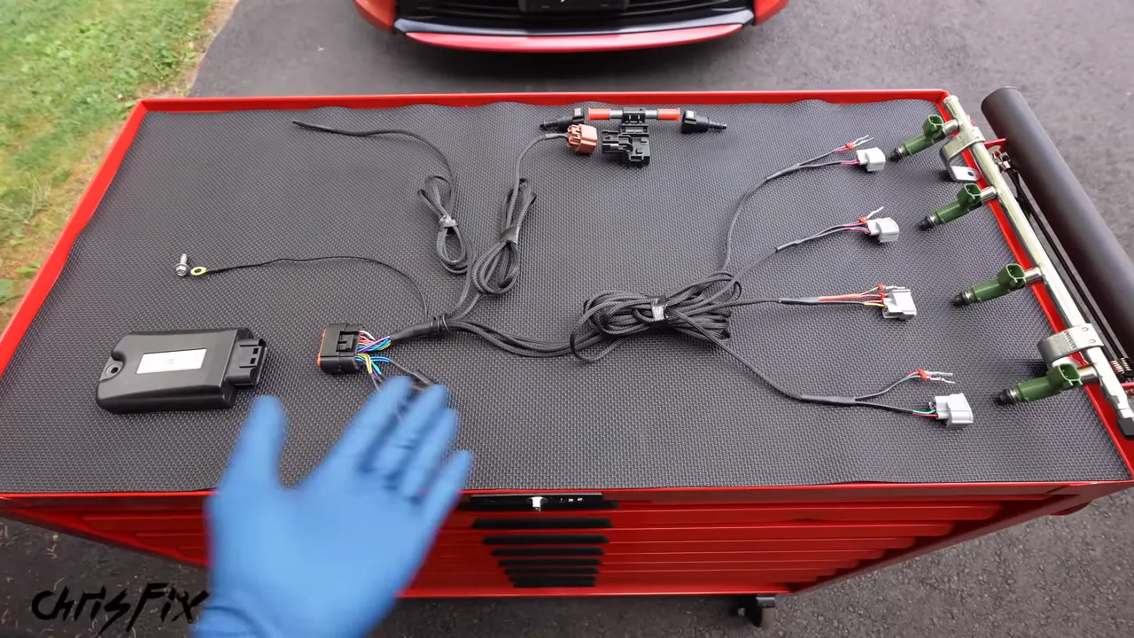
The ethanol sensor measures the blend actually passing through the fuel line. That is what allows the system to handle gasoline, E85, and mixtures in between rather than relying on a fixed assumption about what's in the tank.
Tools and supplies
- Common sockets, ratchets, and wrenches.
- A multimeter with continuity mode.
- A fuel line disconnect tool sized for the vehicle.
- Hose-grip pliers.
- A hose cutter and paint marker.
- Safety glasses and towels for residual fuel.
- Wire loom and zip ties.
- Panel-clip tools and a flathead screwdriver, if access panels need removal.
- A torque wrench for reassembly.
A rotary tool and deburring tool are optional. I used them to adapt the original plastic fuel-connector holders for a cleaner finish, but that modification was not necessary for the kit to function.
For transparency, eFlexFuel supplied the kits and supported this project. Before recommending one, I spent about three years testing kits on my drift car and Del Sol, including track use. I did not experience fuel pump, injector, or fuel line problems on those two vehicles. That is my experience, not a guarantee for every car.
|
1. Prepare the Car and Relieve Fuel Pressure
Do not open fuel lines on a hot engine. Let the engine cool completely, wear safety glasses, and keep fuel and vapors away from sparks, flames, and other ignition sources.
The fuel system can remain pressurized after the car is shut off. Disconnecting a line under pressure can spray fuel into your face or across the engine bay.
On this Prius, I disconnected the negative terminal of the 12-volt battery and left the car overnight to allow pressure to bleed down. However, waiting overnight is not proof that every vehicle's fuel system is depressurized. Follow the pressure-relief procedure in your vehicle's service information.
Another method that works on many vehicles is:
- Locate the fuel pump fuse using the owner's manual or fuse diagram.
- Remove the correct fuse.
- Try starting the engine. It may start and stall, or it may not start.
- Crank as directed by the vehicle's procedure to help relieve remaining pressure.
- Switch the vehicle off and disconnect the negative battery terminal before continuing.
Even after relieving pressure, expect some residual fuel. Place towels under connections before opening them, and keep dirt out of every exposed fuel line. If you removed the pump fuse, remember to reinstall it before testing.
2. Create Access to the Fuel Line
On some cars, the fuel supply connection is easy to reach. On this Prius, it is buried behind the engine under the windshield-wiper cowl. Removing the cowl and metal tray gives us enough room to work properly instead of fighting for access.
Remove the wiper arms and plastic cowl
- Remove the wiper-arm retaining nuts. This installation uses a 14 mm socket, and one nut is hidden under a small cap.
- Lift the arms off their mounting shafts. Fold an arm upward slightly if needed, keeping it clear of the hood.
- Release the plastic cowl clips by pressing their tabs inward.
- Remove the small end trim piece needed for clearance, then lift out the cowl.
Remove the wiper assembly and metal tray
- Unplug the wiper motor.
- Release the wiring-harness clips from the assembly and tray.
- Remove the four 10 mm bolts securing the wiper assembly, then lift it out.
- Vacuum leaves and debris out of the tray so the remaining bolts are visible.
- Remove the eleven 10 mm tray bolts, release the plastic divider, and carefully lift out the tray.
- Remove the engine cover.
Now there is room to follow the fuel supply line from the tank-side connection to the fuel rail. Keep the removed hardware organized for reassembly.
3. Plan the Ethanol Sensor and Fuel Hose Routing
Before cutting or assembling anything, figure out where the sensor can sit and how the fuel hose will reach it safely.
I initially thought the original hose was rubber and could accept the sensor inline. It turned out to be a plastic fuel line covered with a protective rubber layer. Do not cut into a plastic fuel line as though it were ordinary rubber hose.
My next routing idea put the hose too close to the exhaust. That was a definite no. The final solution was to remove the original section and use the kit's hose and adapters to route the fuel through the sensor with better clearance.
Disconnect the original fuel line
Release the outer plastic connector holder, place a towel beneath the joint, and operate the quick-disconnect tabs. On the upper connection here, pressing the yellow buttons releases the line.
The fuel-rail connection needs a fuel line disconnect tool. Fit the tool around the tube and push it into the connector to release the internal retaining mechanism, then pull the connector off.
If access makes that difficult, hose-grip pliers can provide leverage behind the disconnect tool. Use controlled pressure and avoid damaging the tube or fitting. Remove the tool afterward and cover the open lines to keep contamination out.
Match the fitting sizes
This installation uses two different connector sizes:
- Vehicle connections: approximately 7.89 mm, corresponding to the nominal 5/16-inch connection used here.
- Ethanol sensor connections: 9.49 mm fittings supplied for the sensor.
Do not mix them up. The larger sensor fitting is loose on the vehicle's smaller tube and can leak. The correct fitting clicks into place and has very little side-to-side movement. A small amount of movement along the tube can be normal for this connection.
Also, do not clamp a rubber hose directly onto a fuel-rail tube designed for a quick-disconnect fitting. A hose that feels tight in your hand may still come off under pressure.
Sketch the layout first
A quick diagram makes the installation much easier to visualize. My layout uses two 90-degree fittings between the rail and sensor, then straight fittings between the sensor and the tank-side supply line.
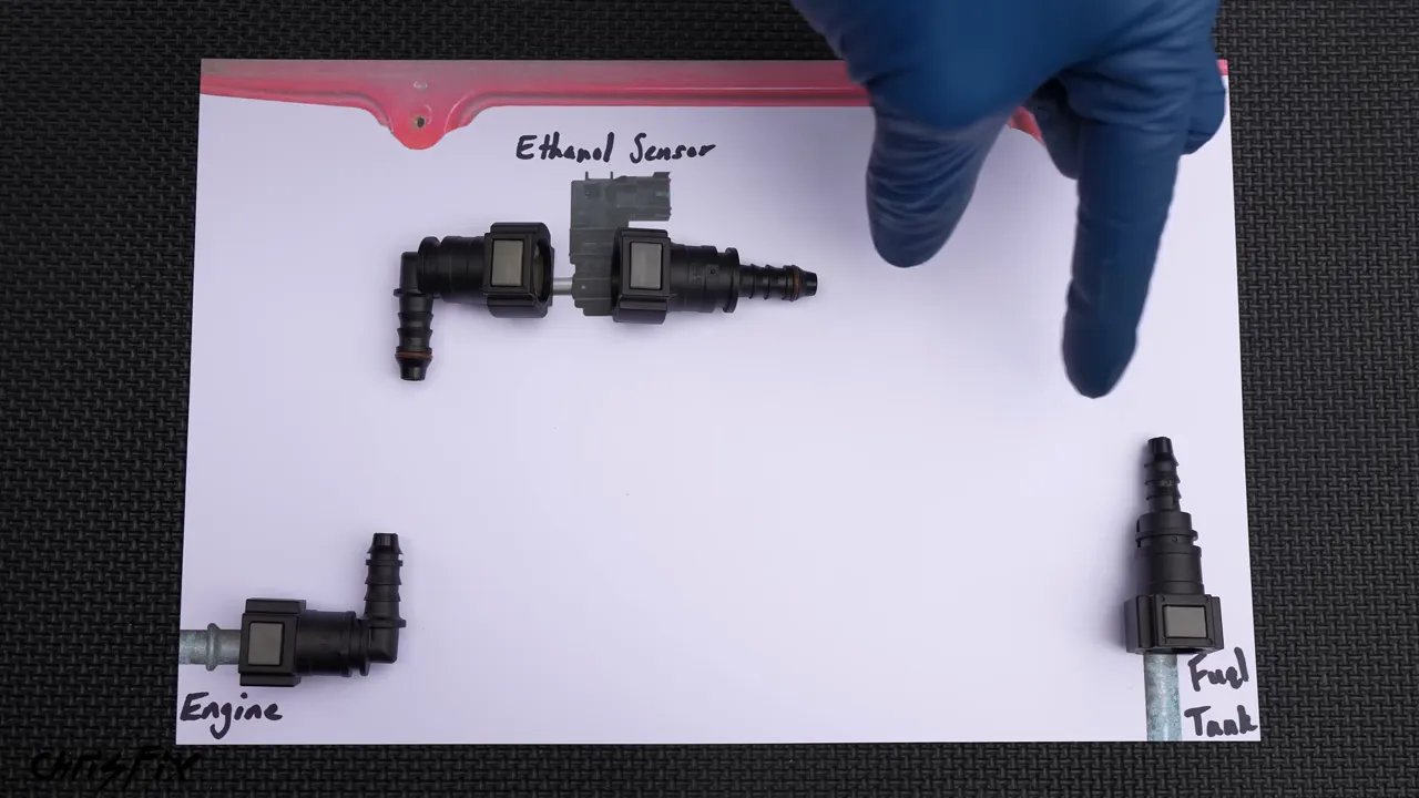
The goal is a smooth route with no kinks, no exhaust exposure, and no rubbing against surrounding components.
4. Assemble and Install the Fuel Hoses
Work one connection at a time. Start with a full length of hose, install the first fitting, and measure the hose in position before cutting it.
- Slide the clamp onto the hose first. It is easy to forget until after the fitting is installed.
- Inspect the fitting. For the supplied fittings, lubricate any O-ring with a little motor oil as directed by the kit instructions. The demonstrated hose fitting without an O-ring installs dry.
- Push the hose fully onto the fitting. It should reach the base, not stop halfway along the barb.
- Position the clamp correctly. Leave a little hose beyond the clamp and tighten it snugly without crushing the plastic fitting.
- Lubricate the quick-connect tube as directed. This helps prevent the internal O-rings from pinching during assembly.
- Push the connector on until it clicks. Give it a few gentle pulls to verify that it is locked.
Use the fuel-injection hose clamps supplied with the kit, not ordinary worm-drive hose clamps. These clamps tighten evenly around the hose without the same pinching action. The wrong clamp can damage the hose or loosen, creating a fuel leak.
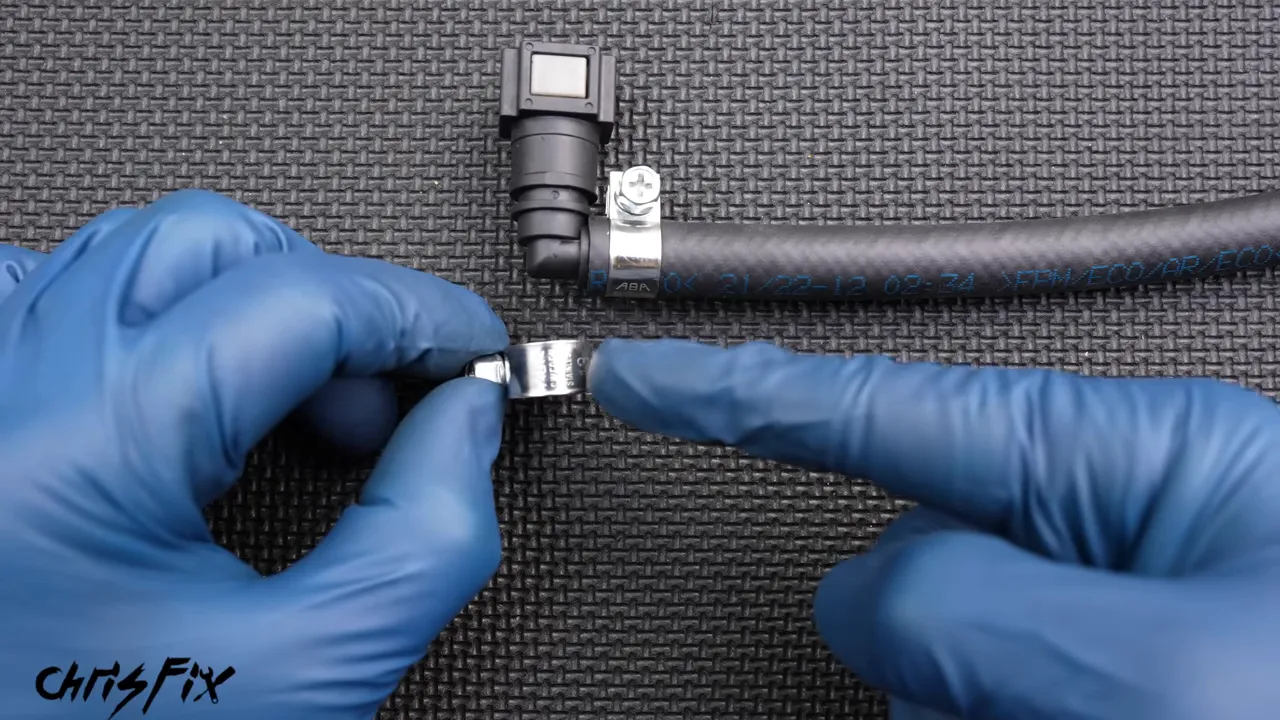
Measure, mark, and cut in position
With the rail-side fitting installed, route the hose toward the intended sensor location. Connect the appropriate fitting to the sensor, hold everything in its final position, and mark the cut with a paint pen.
Make the cut as square as possible. Install the clamp, seat the fitting fully, and snug the clamp. Repeat the process for the hose from the other side of the sensor to the tank-side supply connection.
If pressing a hose onto a fitting is difficult in the engine bay, disconnect the fitting and finish the hose assembly where you have more room. Then reconnect it and check the lock again.
Check clearance and secure the sensor
Before moving on, inspect the complete assembly:
- Every quick connector is clicked in and passes a pull check.
- Every hose clamp is snug and correctly positioned.
- The hoses are not kinked or pulled tight.
- The sensor and fuel lines clear the engine, exhaust, and surrounding parts.
- The sensor is secured so it cannot bounce around during driving.
For the hose used here, I maintained at least a three-inch bend radius. Follow the bend-radius requirement for your supplied hose rather than forcing a tight turn.
I also rotated a nearby factory hose clamp to eliminate contact with the sensor and added protective loom around the new fuel hoses where I wanted extra abrasion protection. Loom is not a substitute for safe routing or adequate heat clearance.
Optional: Reuse the factory connector holders
The original plastic holders did not quite fit around the new connectors and clamps. I carefully clearanced one holder around the clamp and opened up another to fit the larger connector, then deburred the edges and cleaned away the plastic dust.
That allowed the holders to close and limit movement, giving the installation an almost factory appearance. This was an optional finishing step on this car, not a requirement to make the kit work. I modified the outer holders, not the fuel fittings themselves.
5. Identify Injector Polarity and Assemble the Harness
The injector harness goes between each factory injector connector and its injector. Before assembling the supplied connector housings, we need to identify the positive terminal.
Do not rely on wire color alone. On this vehicle, the injectors are ground-side switched: the engine computer controls them through their individual ground circuits, while the positive supply is shared.
Find the common positive terminals
With the battery disconnected and all four injector connectors unplugged:
- Set the multimeter to continuity mode.
- Touch the probes together to confirm the meter beeps.
- Orient two factory injector connectors the same way.
- Check continuity between their terminals.
- Identify the terminals that share continuity across the connectors.
- Verify the result against the other terminals, then check all remaining connectors.
- Mark each confirmed positive side with a red marker.
On this Prius, the shared supply terminals have continuity with one another, while the individual control terminals do not. This method depends on the vehicle's wiring layout. If the results are unclear or differ from this example, use the wiring diagram and kit instructions rather than guessing.
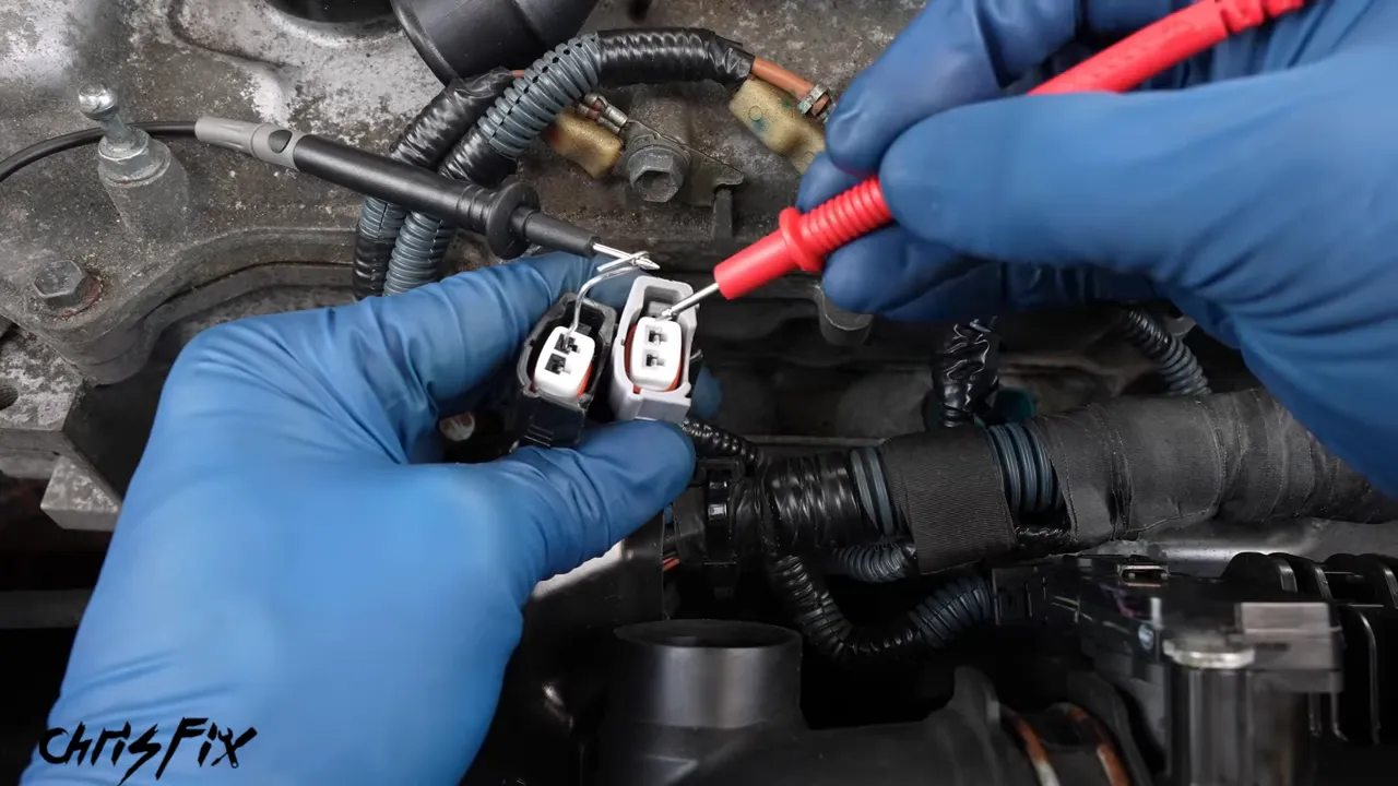
Use suitable probes and avoid forcing anything into the terminals or spreading them apart.
Pin the supplied connector housings
Each injector branch has a connector that fits the injector and an unfinished connector that must mate with the original vehicle harness.
- Test-fit an empty supplied housing to the factory connector to establish its orientation.
- Mark the side corresponding to the positive terminal.
- Remove the housing and insert the kit's red wire into the marked positive cavity until it clicks.
- Give the wire a gentle tug to confirm it is retained.
- Insert the other wire into the remaining cavity until it clicks, then tug-check it.
- Repeat for each injector branch.
Marking the positive cavity before turning the connector around makes it much harder to accidentally reverse the wiring.
Connect one complete branch to each injector
Plug the original vehicle connector into the newly assembled kit connector. Then plug the other connector from that same branch into the corresponding injector.
For this kit, the order of the conversion harness branches does not matter. However, each branch must stay paired with one factory connector and its corresponding injector. Do not cross-connect a factory lead from one cylinder to another cylinder's injector.
Make sure every connector clicks into place, then tuck the branches neatly without pulling on the wiring.
6. Route the Harness and Connect the Computer
Choose the computer's mounting location before bundling the wiring. It needs to be away from engine and exhaust heat, high-voltage wiring, and the alternator on a conventional vehicle.
On this Prius, I chose a location beside the original vehicle computer, away from the orange high-voltage cables. Do not disturb those cables or components during this installation.
Place the temperature probe
Position and secure the temperature probe near the engine as directed by the kit instructions. I tucked it near the injectors so it could sense engine warmth and help the conversion computer distinguish a cold start from a hot start.
Organize and protect the wiring
Start at the injector branches and work toward the main connector, straightening the harness as you go. Put the wires into loom to protect against chafing and make the installation look tidy.
Route the harness around the engine with clearance from heat, sharp edges, and moving parts. On this car, the main harness runs beneath the brake master cylinder toward the computer location.
- Plug the main harness into the conversion computer until it clicks.
- Connect the ground lead to a suitable clean metal grounding point. I used an existing factory chassis ground.
- Route the ethanol-sensor lead to the sensor and click it into place.
- Gather excess wire neatly and secure it with zip ties.
- Secure the main harness so it cannot flap around or rub.
Reconnect any vacuum lines, electrical plugs, or other components moved for access. I like reconnecting a temporary disconnection as soon as the routing work is finished so it cannot be forgotten.
7. Start the Engine and Check for Leaks
Leave the wiper cowl and tray off for the initial test so the new connections remain visible. Before restoring power, remove fuel-soaked materials and make sure there are no spilled fuel or accumulated vapors. Reconnecting a battery can create a spark.
Restore the fuel pump fuse if removed, reconnect the negative battery terminal, and follow the vehicle and kit instructions for pressurizing the system and starting the engine.
Check every opened or added fuel connection immediately:
- Both ends of the ethanol sensor.
- The tank-side supply connection.
- The fuel-rail connection.
- Every hose-to-fitting joint.
If there is any leak, shut the vehicle off immediately. Do not tighten or disconnect a pressurized connection. Relieve the pressure safely before correcting the problem.
Verify operation in the app
Once the installation is dry and leak-free, check the kit's app. On the first start, mine showed:
- An engine RPM reading.
- About 10 percent ethanol in the gasoline already in the tank.
- A temperature reading of approximately 120°F from the kit's probe.
- Four orange injector indicators, showing that all four were operating.
- A device-status screen reporting normal operation.
In this app, an inactive injector would appear gray. Check the device status as well as the main display. The app helps verify the electronics, but it does not replace a physical fuel-leak inspection.
8. Reassemble the Cowl and Secure the Computer
With the initial checks complete, shut the vehicle off and reinstall the access components. This is also a good opportunity to clean the tray before putting it back.
For this Prius, reassembly is:
- Install the metal tray and its eleven retaining bolts.
- Snap the plastic divider back into place.
- Install the wiper assembly and tighten its four bolts.
- Refit all wiring clips and reconnect the wiper motor.
- Snap the plastic cowl into position.
- Refit the wiper arms, tighten their nuts, and replace the nut cover.
- Reinstall the end trim and engine cover.
The specifications used on this car were 4 ft-lb for the wiper-assembly bolts and 17 ft-lb for the wiper-arm nuts. Those are vehicle-specific values, not universal specifications.
Mount the computer without blocking service access
The computer can be mounted using its mounting hole or another method permitted by the manufacturer. I used hook-and-loop fastener with VHB adhesive on the fuse-box cover so I could move the computer aside when accessing the fuses.
Clean both mounting surfaces with alcohol and let them dry. Apply the fastener to the computer, attach the mating pieces, remove the adhesive backing, and press the assembly firmly into place. Attaching the mating pieces first makes alignment easy.
Keep the bypass plug handy
The supplied bypass block plugs into the main harness in place of the conversion computer. It restores the injector circuit's normal path if the conversion computer needs troubleshooting.
The bypass does not make E85 safe to run without the conversion computer. It is intended for normal gasoline operation. If the tank contains a high-ethanol blend, do not simply bypass the computer and continue driving. Follow the manufacturer's recovery instructions.
I keep the bypass plug in the glove box. Any unused injector expansion connections on this harness remain capped and secured out of the way.
9. Add E85 and Confirm the Blend
Only add E85 after compatibility, installation, leak checks, and device checks are complete.
I added an E85 label inside the fuel door to identify the conversion. A label documents the modification; it does not replace proper installation or compatibility verification.
For the first fill, the Prius had about four gallons remaining in its roughly twelve-gallon tank. I added canned E85 because I did not have a convenient local pump. The fuel used for this test was labeled 112 octane, which is not a rating to assume for every E85 source.
After the fuel reached the sensor, the app showed approximately 60 percent ethanol. That made sense because the E85 had mixed with the gasoline already in the tank.
That is exactly why the ethanol sensor matters. The computer responds to the actual blend instead of assuming every fill is pure gasoline or exactly 85 percent ethanol.
With the connections dry, all injectors operating, the harness protected, and the computer secured, the car was ready for its test drive. Take your time with the details, especially fitting sizes, injector polarity, and hose routing. A clean installation should not just look close to factory. It should be secure, serviceable, and thoroughly checked before you put it to work.


