A rattling noise on startup can sound pretty scary, especially when it comes with hesitation, misfires, and a check engine light. On this 2008 Honda Accord with the 2.4-liter engine, the problem was a bad variable valve timing control actuator, commonly called the VTC actuator or cam phaser.
The good news? We can replace the VTC actuator without removing the camshaft. Removing the exhaust cam sprocket gives us enough room to slide the actuator out, install the replacement, and put everything back together. That avoids disturbing the camshaft bearings and the careful loosening and tightening sequences required to remove the cam.
This guide follows that repair from diagnosis through the final test drive. The exact access points, timing marks, torque specifications, and actuator installation procedure apply to the Honda engine shown. Other variable valve timing engines use similar principles, but do not assume this shortcut or these specifications apply to yours.
Important: This is an interference engine. Incorrect valve timing can allow the pistons and valves to collide. Have the service information for your exact vehicle available, and stop if you cannot verify the timing. Honda owners can find factory service information through Honda’s technical information portal.
What You'll Learn
- Check oil level, startup symptoms, and timing alignment before blaming the VTC actuator alone.
- Removing the exhaust sprocket provides actuator clearance without removing the camshaft on the Honda engine shown.
- Support the timing chain continuously to prevent it from dropping or losing engagement inside the engine.
- Verify fixed camshaft and crankshaft timing marks after hand rotation before starting the engine.
Table of Contents
- 1. Diagnose the Startup Rattle Before Buying Parts
- 2. Gather the Tools, Parts, and Supplies
- 3. Clean the Engine and Remove the Valve Cover
- 4. Access the Crankshaft and Set Top Dead Center
- 5. Release Timing Chain Tension
- 6. Remove the Old VTC Actuator Without Removing the Camshaft
- 7. Install and Time the New VTC Actuator
- 8. Verify Timing Before Starting the Engine
- 9. Reseal the Timing Chain Tensioner Cover
- 10. Replace the Valve Cover Gasket and Spark Plug Tube Seals
- 11. Change the Oil if It Is Due
- 12. Start the Engine and Confirm the Repair
1. Diagnose the Startup Rattle Before Buying Parts
Replacing parts without diagnosing the problem costs time and money, and it might not fix anything. Start with the symptoms, check the oil, and read the trouble codes.
Read the check engine codes
This Accord had several symptoms:
- A check engine light.
- Hesitation and poor acceleration.
- Reduced fuel economy.
- Misfires.
- A brief engine rattle on startup.
I used a Bluetooth OBD2 scanner plugged into the diagnostic port under the dashboard. With the ignition in the run position and the engine off, read the engine trouble codes.
The code on this car was P1009, VTC advance malfunction. That points us toward the variable valve timing system, but it does not prove the actuator is the only possible cause.
A worn timing chain can also cause a timing-related fault, particularly on an engine that has been run low on oil. We will check the relationship between the crankshaft and camshaft timing marks once the valve cover is off.
Check the oil and listen after the engine has been sitting
Before starting the engine, check the oil level. Low oil can make the actuator rattle, so do not skip this simple check. On this car, the oil reached the upper mark on the dipstick.
For the startup test, let the engine sit without running for roughly three to six hours. “Cold start” describes an engine that has been sitting, not necessarily cold weather.
The characteristic noise on this Accord was a brief rattle immediately after starting. It did not continue while the engine ran, and restarting a warm engine did not immediately reproduce it. The rattle returned after the car sat for several hours.
With the correct oil level, the P1009 code, and that startup noise, the actuator was the leading suspect. The timing checks later in the repair provided another important piece of the diagnosis.
2. Gather the Tools, Parts, and Supplies
Most of this job uses ordinary hand tools. The actuator bolt can be extremely tight, though, so have a long breaker bar ready.
- Ratchets, extensions, and metric sockets, including 10, 12, 17, and 19 mm.
- A wrench that fits the camshaft holding flats securely.
- A long breaker bar.
- Torque wrenches suitable for both small cover fasteners and the larger sprocket bolts.
- Pliers, a flathead screwdriver, and a rubber mallet.
- A plastic gasket scraper, cleaning alcohol, and clean towels.
- A paint marker, zip ties, and suitable chain supports.
- Degreaser and detailing brushes.
- The correct threadlocker and RTV gasket maker for the repair.
- A replacement VTC actuator and its new mounting bolt.
- A valve cover gasket set, including spark plug tube seals and fastener sealing washers.
- A floor jack, jack stands, wheel chocks, and safety glasses.
Confirm that the replacement VTC actuator and valve cover gasket set fit your exact engine before taking anything apart.
For this particular repair, my friend had received a dealer quote of around $1,000. The parts I used cost a little over $100, putting the potential savings at roughly $900, not counting tools or additional problems. That is a pretty good reason to take your time and do the job carefully.
3. Clean the Engine and Remove the Valve Cover
Make room and keep dirt out
On this Accord, the hood prop can be moved to a second support position that holds the hood higher and gets the prop out of the work area. Support the hood securely before moving it.
Next, clean around the valve cover before loosening any fasteners. Once the cover comes off, dirt can fall directly onto the camshafts, valvetrain, and into the engine.
- Blow loose dirt and dust away with compressed air or a leaf blower while the engine is still closed.
- Apply degreaser around the valve cover and surrounding dirty areas.
- Let it soak briefly, then agitate the grime with a brush.
- Wipe everything clean with an old microfiber towel.
I cleaned the rest of the engine bay, too, because I could not leave one clean part surrounded by dirt. That extra detailing is optional. Keeping debris out of the open engine is not.
Clear the hoses, brackets, and ignition coils
With the area clean, remove the components that prevent the valve cover from lifting off:
- Unbolt the power steering hose hold-down using a 10 mm socket and carefully position the hose out of the way.
- Move the clamps on the EVAP and vacuum hoses, then disconnect the hoses.
- Remove the two bolts securing the hose assembly to the valve cover and move the assembly aside.
- Remove the four 10 mm bolts securing the ignition coil cover, then lift off the cover.
- Remove each ignition coil’s retaining bolt, lift the coils out, and position the coils and harness behind the engine without straining the wiring.
- Remove the dipstick and place it somewhere clean.
A useful hose-removal trick is to twist the hose gently from side to side before pulling it off. That breaks its grip on the fitting and makes removal much easier.
The spark plugs can stay installed for this procedure.
Lift off the cover and upper chain guide
Remove the six valve cover retaining nuts and their rubber sealing washers. If a washer stays stuck, carefully lift it free without damaging the surrounding surface.
If the cover is stuck to the gasket, gently tap it with a rubber mallet to break the seal. Lift it away without dropping dirt into the engine.
Now you can identify the intake camshaft, exhaust camshaft, and VTC actuator at the timing-chain end of the intake cam.
Remove the upper timing chain guide using a 12 mm socket. Keep track of the two bolts: one has a longer head, and they need to return to their original positions. Set the guide on a clean surface.
Inspect for sludge before continuing
The top end of this roughly 200,000-mile engine looked clean, with no heavy sludge. That is what we want.
Thick, black, tar-like deposits are a reason to pause. Replacing an oil-operated timing component without addressing a heavily contaminated engine risks another failure. The contamination needs its own diagnosis and cleaning plan, which may include appropriate oil changes and a suitable additive under vehicle-specific guidance. Do not treat the actuator replacement as a cure for a sludged-up engine.
4. Access the Crankshaft and Set Top Dead Center
Raise and support the car
Chock the rear wheels, lift the front of the car at an approved jacking point, and lower it onto properly positioned jack stands on a firm, level surface. Never rely on the hydraulic jack alone.
Remove the passenger-side front wheel. I also keep the removed wheel underneath the car as an additional precaution, but it is not a substitute for correctly placed stands.
Remove the wheel-well splash shield if fitted. This car was missing that shield, so the crankshaft pulley and timing chain tensioner access cover were already exposed.
Remove the three 10 mm bolts from the tensioner access cover. Carefully separate the cover from its RTV seal without gouging the mating surface.
Find the correct crankshaft timing mark
Place a 19 mm socket on the crankshaft pulley bolt. Turn the engine by hand clockwise, its normal direction of rotation on this engine.
The pulley has multiple marks, and using the wrong one will throw off the whole setup. The relevant group includes three closely spaced marks and a separate mark. The separate mark, originally painted white, is the top dead center reference used here.
On an older engine, the paint may be faded, so identify the actual mark rather than relying only on its color.
Align the camshaft and crankshaft marks together
At the cam sprockets, look for two sets of references:
- The punch mark on each sprocket should face upward.
- The horizontal timing lines on the two sprockets should face one another and line up.
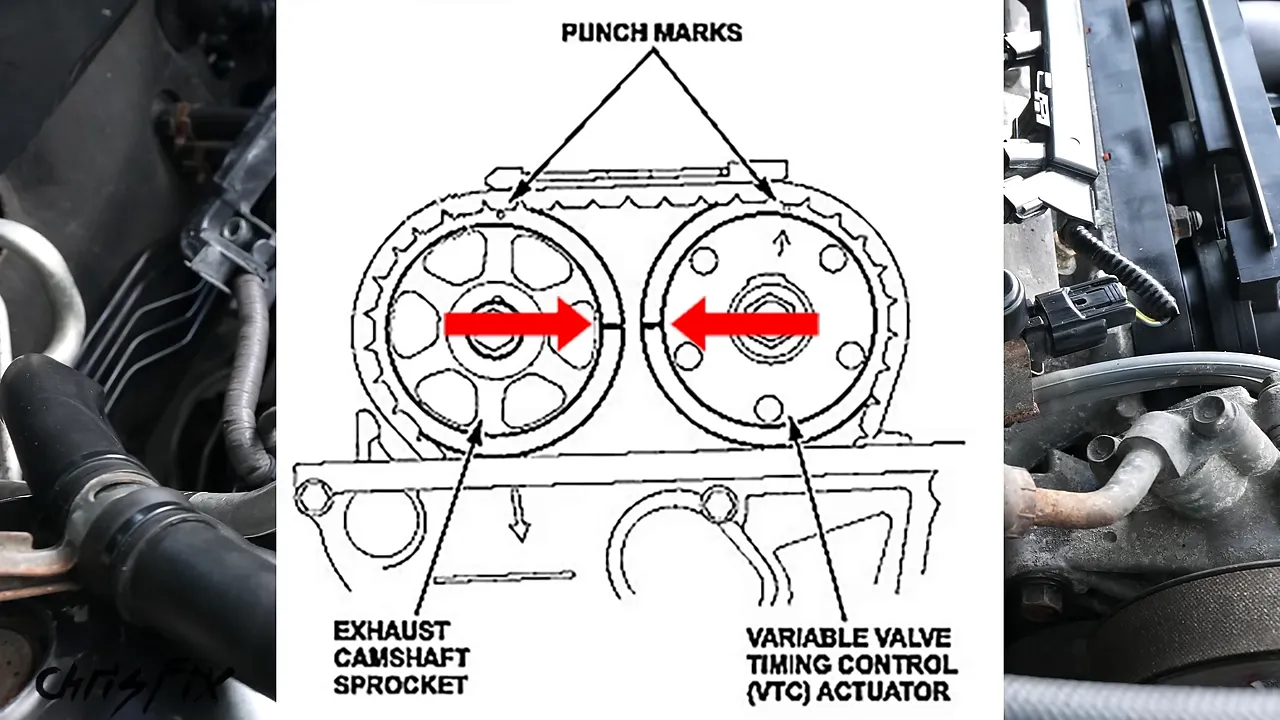
Rotate slowly as the cam marks approach alignment. Then look down at the crankshaft pulley and verify that its separate TDC mark aligns with the pointer on the engine.
All the references must agree. If the cam marks align but the crankshaft mark does not, the chain may be worn or the timing may have shifted. Investigate that before continuing with an actuator-only repair.
This Accord’s marks lined up correctly, so we could continue. Establishing TDC now gives us a reference for reassembly, but it does not eliminate the need to preserve and recheck the timing throughout the job.
5. Release Timing Chain Tension
Through the access opening, locate the automatic timing chain tensioner and its locking mechanism.
- Turn the crankshaft counterclockwise only a small amount, enough to move the tensioner lock and expose its pin hole.
- Insert a suitable retaining pin through the hole to hold the mechanism.
- Turn the crankshaft clockwise back to the established TDC position.
This small reverse movement is specific to the tensioner-release procedure shown here. It is not a reason to rotate the engine backward generally.
The chain now has slack for the sprocket work. From this point onward, keep control of the chain and avoid unnecessary crankshaft or camshaft movement.
6. Remove the Old VTC Actuator Without Removing the Camshaft
Break the actuator bolt loose
Hold the intake camshaft using its machined wrench flats, then loosen the actuator’s center bolt with a 17 mm socket and a long breaker bar. Counterhold the camshaft rather than asking the timing chain to resist the loosening force.
Honda’s referenced wrench size was 24 mm, but that wrench had noticeable play on this particular camshaft. A 23 mm wrench fit securely. Use the size that fully engages the flats without slop, and do not force an undersized wrench onto them.
Holy smokes, the actuator bolt on this car was tight. I ultimately used an induction heater to help release it rather than using an open flame near the timing chain.
Heat is not a casual troubleshooting step. An induction heater can make the fastener dangerously hot and damage nearby components if misused. If the bolt will not release with the proper holding tools and breaker bar, stop and get appropriate help rather than applying uncontrolled heat.
Once the bolt breaks loose, leave it partially threaded while preparing the exhaust sprocket.
Mark the chain and support it before removing either sprocket
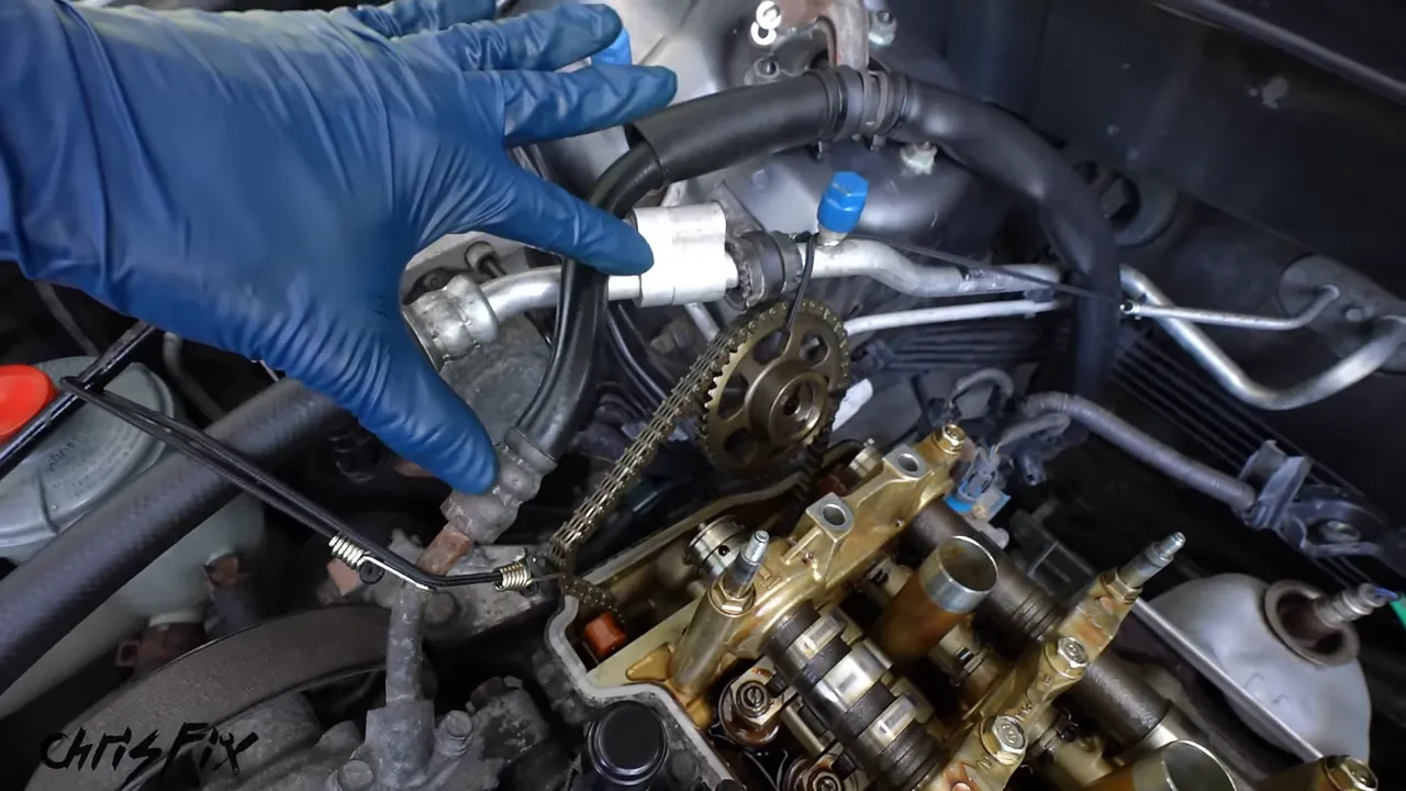
The factory procedure described for this repair involves camshaft removal. Instead, we are removing the exhaust sprocket to make room for the VTC actuator to slide off the intake cam.
- Zip-tie the timing chain to the exhaust sprocket so their relationship cannot change.
- Use a paint marker to mark the chain at the punch mark on each sprocket.
- Prepare bungee cords, ties, or another suitable support to hold the chain up as the sprockets come off.
- Counterhold the exhaust camshaft at its wrench flats and loosen the exhaust sprocket bolt.
Have the chain support ready before removing the sprockets. Do not wait until the chain is already hanging loose.
If the chain drops or loses engagement with a sprocket deeper in the engine, the timing cover may need to come off to restore and verify its position. That turns this into a much larger repair.
Slide the sprockets off carefully
Remove the actuator bolt and exhaust sprocket bolt completely. Carefully work the actuator and exhaust sprocket off their camshaft ends, moving each side a little at a time rather than forcing one edge.
Keep the chain lifted and lightly tensioned throughout. With the exhaust sprocket moved aside and the chain supported, slide the old actuator out.
7. Install and Time the New VTC Actuator
Compare the parts and check the unlocked position
Compare the replacement actuator with the old one before installing it. Check the overall design, sprocket, mounting features, and replacement bolt.
There is an important difference in the positions shown here: the new actuator arrives unlocked, while the old actuator is in its locked position. The keyway orientation makes that difference visible.
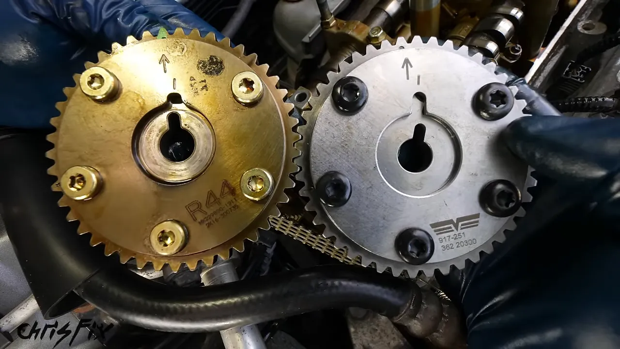
For this replacement, leave the actuator unlocked during installation and tightening. Do not rotate it into the locked position prematurely. Confirm the required position using the instructions for your exact replacement part.
Seat and tighten the actuator
The actuator is keyed to the camshaft, so it fits in only one orientation. Slide it onto the camshaft and gently position it until the key engages and the actuator seats fully. Do not keep rotating it after it seats.
On this repair, I applied high-strength removable threadlocker to the end of the new bolt’s threads and motor oil to the threads and shank, then hand-threaded the bolt.
Follow the specified fastener preparation for your exact application. Oil and threadlocker affect tightening conditions, so do not substitute products or combine them without checking the service and product instructions.
Counterhold the camshaft and torque the actuator bolt to 83 lb-ft for the engine shown. After tightening, turn the actuator into its locked position. The click confirms engagement.
Refit the chain and exhaust sprocket
Place the chain onto the new actuator, matching the painted chain reference to the actuator’s punch mark. Check the actual tooth engagement closely. A mark that looks approximately aligned is not enough; the sprocket teeth must sit correctly between the chain links.
Then bring the exhaust sprocket back onto the exhaust camshaft while maintaining chain support. The sprocket is keyed, so it also fits in only one orientation. A very small, controlled movement at the camshaft flats helped walk it into position on this car.
Before tightening the exhaust sprocket, verify:
- The intake chain paint mark aligns with the actuator punch mark.
- The exhaust chain paint mark aligns with the exhaust sprocket punch mark.
- The two inward-facing cam timing lines align.
- The crankshaft remains at the established TDC reference.
Prepare the exhaust sprocket bolt as specified, start it by hand, counterhold the camshaft, and torque it to 51 lb-ft for this engine.
Cut off the zip tie while holding onto both pieces. Do not let a piece fall down inside the timing cover. Remove the temporary supports only when the chain and sprockets are securely in place.
If the sprocket will not slide on
Even with the tensioner pinned, there may not be enough slack to refit the exhaust sprocket easily. Do not force it.
The alternative shown is to remove the two 10 mm bolts securing the tensioner and withdraw the tensioner to release more chain tension. Support the chain especially carefully because it becomes looser. If you use this option, reinstall and secure the tensioner according to the service procedure before proceeding.
8. Verify Timing Before Starting the Engine
Remove the tensioner retaining pin so the automatic tensioner can take up the chain slack.
Now rotate the crankshaft clockwise by hand through at least two complete revolutions. Move slowly and stop if you encounter abnormal resistance. Do not use the starter to perform this check.
Return to the same TDC reference position and verify:
- Both cam sprocket punch marks face upward.
- The inward-facing cam timing lines align.
- The crankshaft pulley TDC mark aligns with the engine pointer.
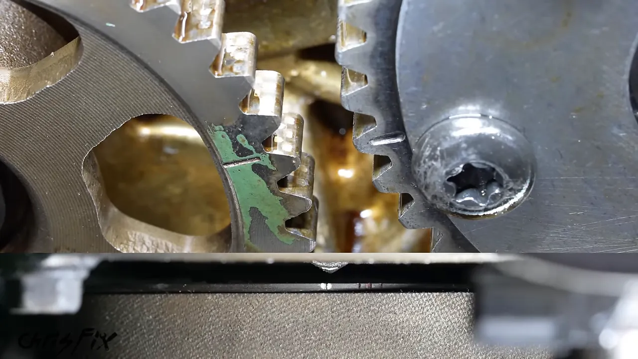
The paint marks on the chain will no longer necessarily align with the sprocket marks after rotation. They were assembly references. At this stage, use the fixed camshaft and crankshaft timing marks.
If the marks do not agree, do not start the engine. Correct the timing first.
Once timing is verified, reinstall the upper chain guide. On this engine, the bolt with the longer head goes on the left in the working orientation shown. Torque both guide bolts to 16 lb-ft, and check that the chain runs in the center of the guides.
9. Reseal the Timing Chain Tensioner Cover
Good sealing starts with clean, smooth mating surfaces. New RTV over old residue is asking for a leak.
- Remove the old RTV from the cover using a plastic scraper.
- Wipe the cover’s mating surface with alcohol to remove oil.
- Place a clean towel in the engine opening to catch debris while cleaning the engine-side surface.
- Scrape away the old RTV, wipe the surface clean, and remove the towel.
A metal scraper can gouge the sealing surface and create a path for oil to escape, so stick with plastic.
Apply a small, continuous bead of RTV around the cover perimeter and around the bolt holes. The mating surfaces are flat, so there is no need for a huge bead.
I used a quick-setting gasket maker with instructions to assemble and torque within five minutes, followed by a one-minute return-to-service period after tightening. Those times apply to that specific product. Other RTV formulas require different assembly and curing times, so follow the package rather than assuming all gasket makers work the same way.
Carefully position the cover without wiping the fresh bead against surrounding parts. Starting the upper two bolts in the cover helps guide it into place. Hand-start all three bolts, then torque them to 9 lb-ft for this engine within the sealant’s assembly window.
For the sealant container used here, leaving a small amount protruding beyond the nozzle created a cured plug for later use. Follow your product’s storage instructions.
Reinstall the splash shield if removed and refit the wheel. I used 100 lb-ft on the lug nuts during this repair, but verify the specified wheel-nut torque for your exact vehicle and wheels rather than treating that value as universal.
10. Replace the Valve Cover Gasket and Spark Plug Tube Seals
With the cover already off, replace the seals now rather than reusing old rubber and risking an oil leak.
Replace the four spark plug tube seals
These seals keep oil out of the spark plug wells. They have metal reinforcement, so old seals can be surprisingly stubborn.
Carefully work a flathead screwdriver between the old seal and its seat, gently tap it into position, and lever the seal out. Avoid scratching or distorting the valve cover.
For the seals used here, a light coating of motor oil around the outside edge helped the new seals press into place. Center each seal and seat it evenly, following the gasket manufacturer’s installation instructions.
Install the perimeter gasket and corner RTV
Pull the old perimeter gasket out of its channel. Install the new gasket in the same orientation and press it fully into the groove all the way around.
This Honda also needs small dabs of RTV at four specified corner joints. These are the junctions where adjoining castings meet beneath the valve cover gasket. Use just enough to seal the joint, not a thick layer around the entire gasket.
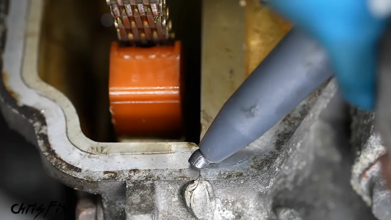
Lower the valve cover onto the cylinder head without dislodging the gasket. Gently position it until it seats fully.
Install the six new sealing washers with their rubber sides facing down, then hand-start the nuts. Tighten them in a crisscross pattern to seat the cover evenly, finishing at 9 lb-ft for this engine.
Reconnect everything around the cover
- Seat all four ignition coils onto the spark plugs and torque their retaining bolts to 9 lb-ft.
- Reinstall the ignition coil cover and snug its four fasteners.
- Reattach the power steering hose hold-down.
- Reinstall the two bolts holding the EVAP hose assembly.
- Reconnect the vacuum and EVAP hoses and return the clamps to their proper positions.
- Wipe the dipstick clean and reinstall it.
Take one more look around the engine bay for loose hardware, disconnected hoses, tools, towels, and anything left near moving components.
11. Change the Oil if It Is Due
An oil change was not required simply to replace this actuator, but this car’s maintenance display showed 15 percent oil life remaining. Since it was already raised, it made sense to finish the job with fresh oil and a filter.
- Place a drain pan underneath and remove the oil drain plug.
- Allow the oil to drain completely, then reinstall the plug using the specified sealing washer and tightening procedure.
- Remove the old filter and install the replacement according to its instructions, lightly lubricating its sealing gasket.
- Refill with the specified oil and check the dipstick level.
I prefilled the replacement filter for this installation and marked the mileage on it with a paint pen. That makes the next service check easy.
The oil used in this Accord was full-synthetic 5W-20. Use the grade and quantity specified for your engine, and do not overfill it.
Once all work underneath is complete, remove the stands using the proper lifting procedure and lower the car.
12. Start the Engine and Confirm the Repair
Now for the moment of truth.
Start the engine and listen carefully. On this Accord, the startup rattle was gone. The idle was buttery smooth, and there was no check engine light.
Let the engine reach operating temperature, inspect the resealed areas for leaks, and scan for trouble codes. I let this car idle for about 25 minutes before confirming that it was running well with no codes present.
Then came a roughly 30-minute road test. Acceleration was smooth, the misfires were gone, and the check engine light did not return.
Since the original rattle appeared after the engine had been sitting, include another startup check after a similar rest period when confirming the repair.
The big things are diagnosis, cleanliness, chain control, and timing verification. Get those right, use the correct specifications, and this method lets you replace the VTC actuator without disturbing the camshaft assembly. A quiet startup and a smooth-running engine make all that careful work worth it.


